Chapter 6 Trusses and frames
Download this chapter by section
- 6.0Introductionstudy PDF
- 6.1Method of jointsstudy PDF+ solutions
- 6.2The method of sectionsstudy PDF+ solutions
- 6.3Solving trusses on a computerstudy PDF+ solutions
- 6.4Frames and structuresstudy PDF+ solutions
- 6.5Advanced truss concepts: determinacystudy PDF+ solutions
Here we consider collections of parts designed to hold something up or in place. Emphasis is on trusses, assemblies of straight bars connected by pins at their ends. Trusses are analyzed by drawing free-body diagrams of the pins (method of joints) or of bigger parts of the truss (method of sections). Frameworks, built with other than two-force bodies are also analyzed by drawing free-body diagrams of parts. Trusses and frames can be rigid or not and redundant or not, as can be determined by the equilibrium equations.
Many structures are built from two or more parts. If the parts are well-modeled as rigid, and the connections between them are also well-modeled as rigid,
then the separateness of the parts is not visible to the laws of mechanics. The collection is then, effectively, a single object. And the best we can do with statics is to treat the group as one object. And this has been the approach of the previous chapter.
Either by accident or design, however, the connections between solid parts often are not well-modeled as rigid. Rather, the connections are sometimes reasonably approximated as freely allowing some relative motion.
This chapter concerns the analysis of arrays of parts connected by these means:
-
•
with pin joints. A pin joint allows relative rotation of the parts; it does not transmit moments. Forces are transmitted in all directions. The pin connection is, by far, the most common model for connections in structures.
-
•
a round pin in a slot. A pin in slot allows relative rotation of the two parts and relative motion in one direction. The only force transmitted is orthogonal to the slot.
-
•
square pin in a slot (or shaft around a rod). This connection allows sliding in the slot but does not allow rotation. A force orthogonal to the slot is transmitted; so is a moment.
As is always the case at free-body diagram cuts, if translation or rotation is assumed to be freely allowed there is no force or moment, respectively. If translation or rotation are restricted there is a corresponding force or moment. The list above includes all of the standard models for motion-allowing connections between parts (see the table on page Back tables). In 3D the array of standard connections is more complex, as discussed in Chapter 3.
In the previous chapter we only considered one object, and thus one free-body diagram, at a time. Here we need to consider, all at once, a collection of objects and the associated collection of free-body diagrams. The new skills that are thus needed are
-
•
Use of the principle of action and reaction in the representation of forces on the free-body diagrams of pairs of interacting objects, and
-
•
The solution of a larger number of simultaneous equilibrium equations.
We start with the analysis of trusses, structures built out of straight bars connected to each other by pins at their ends.
6.1 Introduction to trusses and the method of joints
Trusses are good.
Trusses are useful in engineering practice, they are easy to analyze, and they provide a good example of more general structural concepts. Your main goal here is to learn ‘truss analysis’, how to find the tensions in the bars of a given truss. But first, what is a truss and why are trusses so common?
You can quickly get a tactile sense of the truss concept. Get 9 short sticks and 9 rubber bands††margin: Some useable supplies are surely on hand. For sticks you can use pencils, pens, paper tightly rolled and taped into tubes, chopsticks, popsicle sticks, big wooden matches, knitting needles, barbecue skewers, plastic drinking straws, straw from a broom, Tinkertoy rods, table knives, or strips cut from cardboard. Similarly rubber-bands can be replaced with masking, scotch or duct tape, used chewing gum, lashings using thread or string, hot-melt glue, or (for some of the sticks above) with a paperclip punched through the sticks and bent to make a home-made rivet. .
Put them together a few different ways and feel the resulting rigidity or lack thereof.
-
a)
A ‘V’ deforms. First join two sticks tightly together with a rubber band so that they cannot easily slide along the connection, as in fig. 6.1a. Despite the tight joint connection you can feel that the sticks rotate relative to each other relatively easily; it is easy to open and close the upside-down V.
-
b)
A triangle is sturdy. Add a third stick to complete the triangle (fig. 6.1b). The relative rotation of the first two pencils is now almost totally prohibited. Even though each joint on its own made a relatively flexible V, together the 3 joints make a very stiff triangle.
-
c)
A square deforms. Now tightly strap four sticks into a square as in fig. 6.1c, making 4 rubber band joints at the corners. Put the square down on a table. The sticks don’t stretch or bend visibly, nor do they slide much along each-other’s lengths, but the connections allow the sticks to rotate relative to each other so the square easily distorts into a parallelogram.
-
d)
Two triangles are sturdy. Now add two more sticks to your triangle to make two triangles (fig. 6.1d). So long as you keep this structure flat on the table, it is also sturdy.
Because a triangle is fully determined by the lengths of its sides and the V and quadrilateral are not, the structures made of triangles are much harder to distort. A triangle is sturdy even without rigid joints. And a V and a square (and a pentagon, etc) are not.
You have just observed the essential inspiration of a truss:
Triangles make sturdy structures.
Swiss cheese
A different way to discover a truss is by means of subtraction. Imagine your first initial design for a bridge is to make it from one huge chunk of solid steel. This would be wildly heavy and expensive. So you could cut holes out of the chunk here and there, greatly diminishing the weight and amount of material used, but not much reducing the strength. Between these holes you would see other heavy regions of metal from which you might cut more holes leading to a more savings of weight at not much cost in strength. In fact, the reduced weight in the middle decreases the load on the outer parts of the structure possibly making the whole structure stronger rather than weaker††margin: Advanced aside: There are three ways that having more material in a structure can make it weaker: 1) the extra material adds to the gravitational load, as for the imagined bridge here, 2) Added material can be wedged in, causing the structure to fight itself (so called locked-in or internal stresses), and 3) material in the wrong place can cause stress concentrations and thus weak spots. . Eventually you would find yourself with very holey swiss cheese, a structure that looks something like a collection of bars attached from end to end in vaguely triangular patterns; like a microscopic picture of spongy bone (fig. 6.2):
As opposed to a solid block, a truss
-
•
Uses less material;
-
•
Puts less gravity load on other parts of the structure;
-
•
Leaves space for other things of interest (e.g., cars, cables, wires, people).
Real trusses are usually not made by removing material from a solid but by joining bars of steel, wood, or bamboo with welds, bolts, rivets, nails, screws, glue, or lashings. Once you are aware, you will notice trusses making up bridges, radio towers, and large-scale construction equipment. Early airplanes were flying trusses (fig. 6.3).
Bamboo trusses have been used as scaffoldings for millennia. Birds have had bones whose internal structure is truss-like since they were dinosaurs.
Trusses are practical, sturdy, and light structures.
But trusses are also prominent near the front of elementary mechanics books because
-
•
They are perhaps the easiest example of a complex mechanical system that a student can analyze;
-
•
They illustrate a variety of more general structural mechanics issues;
-
•
They help build intuition about structures that are not really trusses; the engineering mind can see an underlying conceptual truss where there is no physical truss.
What is a truss?
A truss is a structure made from long narrow bars connected at their ends.
The sturdiness of most trusses comes from the inextensibility of the bars, not the resistance to rotation at the joints (as in the sticks and rubber-band examples at the start of this section). To make the analysis simpler, the relatively small resistance to rotation in the joints (even welded joints) is totally neglected in truss analysis. Thus the interaction of the bars with their neighbors is by forces, with no couples; each bar has one net force acting on each end. So:
An ideal truss is an assembly of two-force members.
Or, if you like, an ideal truss is a collection of bars connected at their ends with frictionless pins. Loads are only applied at the pins. In engineering analysis, the word ‘truss’ refers to an ideal truss even though the object of interest might have, say, welded joint connections.
Had we assumed the presence of welding equipment in your study room, the opening paragraph of this section would have described the welding of metal bars instead of the attachment of pencils with rubber bands. Even with welded-together steel you would have found that the triangles would be much more rigid than the V or square.
Bars, joints, loads, and supports
An ideal truss is a collection of bars connected at frictionless joints at which are applied loads as shown in fig. 6.5b (the load at a joint can be and thus not show on either the sketch of the truss or the free-body diagram of the truss). A truss is held in place with supports which are idealized in 2D as either being fixed pins (as for joint E in fig. 6.5a) or as a pin on a roller (as for joint G in fig. 6.5a). Reaction forces, the forces on the truss at the supports, show on a FBD of the whole truss (fig. 6.5b) and also on a FBD of any joint at a support. Each bar is a two-force body (fig. 6.5c), with the same magnitude of tension pulling away from each end. A joint can be cut free with a conceptual chain saw, fooling each bar stub with the bar tension, as in the free-body diagram of a joint in fig. 6.5d.
The bar tensions can be negative. A bar with a tension of, say, is said to be in compression. A tension of is a compression of .
Elementary truss analysis
In elementary truss analysis you are given the design of a truss and the loads applied to it. Your goal is to ‘solve the truss’ which means you are to find the reaction forces and the tensions in the bars (sometimes called the ‘bar forces’). As an engineer, this allows you to determine the needed strengths for the bars.
The ‘method of free-body diagrams’
Trusses are always analyzed by the same basic method used in all of mechanics, the ‘method of free-body diagrams’.
-
•
Free-body diagrams are drawn of the whole truss and of various parts of the truss.
-
•
The equilibrium equations are applied to each free-body diagram, and
-
•
The resulting equations are solved for the unknown bar forces and reactions.
The ‘method of free-body diagrams’ is classically subdivided into two sub-methods.
-
•
In the method of joints you draw free-body diagrams of every joint and apply the force-balance equations to each free-body diagram.
-
•
In the method of sections you draw a free-body diagrams of one or more parts of the structure, each of which includes 2 or more joints and apply force and moment balance to the part or parts.
These two methods can be used separately or in conjunction.
In the rest of this chapter we cover the method of joints, the method of sections, computer solution using the method of joints, and miscellaneous advanced truss topics.
The elementary truss analysis you are about to learn is straightforward and fun. You will learn it without difficulty. However, the analysis of trusses at a more advanced level is mysteriously deep and has occupied great minds from the mid-nineteenth century (e.g., Maxwell and Cauchy) to the present (see, e.g., box 6.5 on page 6.5).
Method of joints
Let’s start with an example.
Example: Derrick arm.
Consider this planar model of the arm of a construction derrick (see fig.6.7). Assume and are known. This truss has joints A-S (skipping ‘F’ to avoid confusion with the load). As is common in truss analysis, we totally neglect the force of gravity on the truss elements
.
The goal is to find the tensions in the bars (the so-called ‘bar forces’).
The method of joints is a subset of the more general method of free-body diagrams. Free-body diagrams are drawn of the joints. Here is the method-of-joints recipe:
-
•
Draw a free-body diagram of the whole structure and write 3 independent equilibrium equations (6 in 3D) and solve for unknown reactions if you can. This step is technically superfluous, but is so-often a time-saver that it’s best to just do it.
-
•
Draw free-body diagrams of all joints, 18 such in the example above.
-
•
For each joint free-body diagram you write the force-balance equations, each of which can be broken down into 2 scalar equations (3 in 3D).
-
•
Solve the joint equations ( in 3D) for the unknown bar forces and reactions. In the example above this is equations for 33 unknown tensions and 3 unknown reactions (which you may have found from the FBD of the whole structure, but need not have).
Solving 36 simultaneous equations is generally only feasible with a computer, which is one way to go about things. However, for simple triangulated structures, like the one in fig. 6.7, you can find a sequence of joints for which hand solution is easy. If you solve the equilibrium equations as you go, there are at most two unknown bar forces at each joint. By this means, the joint force-balance equations can be solved, even for some complex structures, without computers.
Example: Using the FBD of the whole structure
From the free-body diagram of the whole structure (fig. 6.7) we find that
Note, we picked a sign convention for the graphical representation of forces on the Free-Body Diagram (see pages 1.1 and 2.64) and let the algebra possibly generate negative numbers: at S the support pushes on the arm with a force of which is pulling (if )
Note that for tension the order of subscripts is not meaningful. The tension is the same scalar as the tension . is the amount of pulling on joint B and also the amount of pulling on joint C. That the two force vectors are negatives of each other is accounted for by the definition of tension as pulling. This unimportance of the order of subscripts is in contrast with the case of position vectors where is the position vector from B to C (also called ). For position vectors . Summarizing, the subscript order has meaning for but not for .
FBDs of the joints
In the solve-by-hand method of joints, we first find a joint with at most 2 bars connected. Then we work our way through the structure, one joint at a time, picking joints with at most 2 unknown bar tensions. For each joint we will use
Typically many bars in a truss are parallel to the or axis so we often fall into the routine of immediately reducing the above vector equilibrium equation to the component equations
For the truss in fig. 6.7
-
•
Joint B has only two bars connected (see fig. 6.8). Force balance using FBD 6.8 tells us at a glance that
-
•
Now you can draw a free-body diagram of joint A where there are only two unknown tensions (since we just found ), namely and . Force balance gives two scalar equations
which you can solve to find and .
-
•
Next is joint C. Force balance for joint C will tell you and .
-
•
Then you can work your way through the alphabet of joints. Using the bar tensions you have already found you can find, one at a time, joints with only two unknown tensions.
That’s it for the method of joints for simple structures.
Zero-force members
Just by looking at joint B and thinking about the free-body diagram you could probably pick out that bars DB and AB must be zero-force members.
Here we explain the unnecessary but useful trick of recognizing such zero-force members even before systematically using the method of joints. Zero-force members are bars with , like bars AB, BD and CD in the truss of Fig. 6.7. The basic idea is this:
If there is any direction for which only one bar contributes a force on a joint, then that bar is a zero-force member.
In particular:
-
•
At any joint where
-
–
there are no loads, and
-
–
where there are only two unknown non-parallel bar forces, and
-
–
where all known bar-tensions are zero,
then the two new bar tensions are both zero (e.g., joint B in fig. 6.8).
-
–
-
•
At any joint where all bars but one are in the same direction as the applied load (if any), the one bar is a zero-force member (see joints C, G, H, K, L, O, and P in fig. 6.7).
In the truss of fig. 6.7 bars AB, BD, CD, EG, IH, JK, ML, NO, and PQ are all zero-force members. Sometimes it is useful to keep track of the zero-force members by marking them with a zero (see fig. 6.9).
Zero-force members often have a non-zero purpose
Although with the given loading zero-force members have no tension, they are often needed because there are small loads not considered in the basic analysis. These could be from imperfections, or load-induced asymmetries in a structure. This gives the ‘zero-force’ bars a small job to do, a job not noticed by the equilibrium equations in elementary truss analysis, but one that can prevent total structural collapse. Imagine, for example, the tower of fig. 6.10. In a real tower of that design the zero-force members might carry very small loads, say 100 or 1000 times smaller than the tensions (or compressions) calculated for the other bars. But if the zero-force members were removed the tower would collapse. Thus, in practice, you may observe large heavy structures with some very thin bars. Bars which in simple analyzes carry no loads. But bars which prevent structural collapse
Simple and not-simple trusses
Most elementary texts, like this one, start with structures that yield easily to the method of joints. These are structures where you can totally solve the equilibrium equations for the joints, one joint at a time; each new joint introduces two scalar equations and two unknown bar-tensions.
For more complex trusses, this straightforward approach can fail a few ways:
-
•
Some structures are not designed in a straightforward triangulated manner and cannot be solved 2 equations at a time. Although the method of joints may still yield a solution, it may require simultaneous solution of all of the equilibrium equations††margin: In the language of linear algebra: simple structures yield equilibrium equations that are naturally in upper triangular form. More complicated structures do not yield an upper-triangular form. .
-
•
Many structures cannot be solved (that is, the bar tensions can’t be found) by using the laws of statics alone. Such are appropriately called ‘statically indeterminate’ (e.g., see page 7.1).
For this first truss section we only consider structures that are statically determinate and easily solved. See sec. 6.5 for a detailed discussion of static determinacy.
Why aren’t trusses everywhere?
Trusses can carry big loads with little use of material and can look nice (See fig. 6.11). They are used in many structures. Why don’t engineers use trusses for all structural designs? Here are some reasons to consider not using a truss:
-
•
Trusses are relatively difficult to build, involving many small parts††margin: If an Indian says to you ”Go and count the rivets in the Howrah bridge.” she means go away and do something that will take a very long time. The bridge has many rivets (and bars and joints). and thus requiring much time and effort to assemble.
-
•
Trusses can be sensitive to damage when forces are not applied at the anticipated joints. They are especially sensitive to loads on the middle of the bars.
-
•
Trusses inevitably depend on the tension strength in some bars. Some common building materials (e.g., concrete, stone, and clay) crack easily when pulled.
-
•
Trusses often have little or no redundancy, so failure in one part can lead to total structural failure.
-
•
The triangulation that trusses require can use space that is needed for other purposes (e.g., doorways, rooms).
-
•
Trusses tend to be stiff, and sometimes more flexibility is desirable (e.g., diving boards, car suspensions).
-
•
In some places, some people consider trusses unaesthetic. (e.g., the Washington Monument is not supposed to look like the Eiffel Tower).
Nonetheless, for situations where you want a stiff, light structure that can carry known loads at pre-defined points, a truss is often the best design choice.
Three-dimensional trusses
After you have mastered the elementary 2D truss analysis of the previous section, you might wonder
-
•
Do the ideas generalize to 3D? Yes, with only minor elaboration.
-
•
Does at least one of the methods presented always work? Yes, if you just look at the homework problems for elementary truss analysis. And yes again for many practical structures. But some trusses cannot be analyzed by the simple methods. In this section we classify trusses into types. One type, statically determinate trusses, can be analyzed by simple statics methods; other trusses require study of deformations as well as statics.
The concepts for 3D trusses are basically the same as for 2D trusses with these differences;
-
•
In the method of joints, each joint is associated with 3 scalar force-balance equations instead of 2;
-
•
In the method of sections, and in the free-body diagram of the whole structure one has 6 scalar equations instead of 3;
-
•
To hold the structure in place takes at least 6 reaction components instead of 3;
- •
-
•
The rule of thumb for rigidity for a floating truss in 3D is instead of the 2D relation .
(Recall: = number of bars; = number of reaction components; & = number of joints.) There are various ways to think about the number six in the counts above. Assuming the structure is more than a point, six is the number of ways a rigid structure can move in three-dimensional space (three translations and three rotations), six is the number of equilibrium equations for the whole structure (one 3D vector moment, and one 3D vector force), and six is the number of constraints needed to hold a structure in place.
Example: A tripod
A tripod is the simplest rigid 3D structure. With four joints (), three bars (), and nine unknown reaction components (), it exactly satisfies the equation , a check for determinacy of rigidity of 3D structures.
Example: A tetrahedron
The simplest rigid floating structure in 3D is a tetrahedron. With four joints () and six bars () it exactly satisfies the equation which is a check for determinacy of rigidity of floating 3D structures.
A tetrahedron is thus, in some sense, the 3D equivalent of a triangle in 2D.
Example: Geodesic domes
Any closed polyhedron, with each face a triangle of rods, is a rigid structure. This includes a tetrahedron (above), an octahedron, a cube with a diagonal on each face, an icosahedron, and Buckminster Fuller’s geodesic domes.
Well, so Cauchy thought. It turns out that there are some strange non-convex polyhedra that are not rigid. But, for practical purposes, if you see triangles all around the outside of a structure you can assume it’s rigid.
SAMPLE 6.1
The truss shown in the figure carries a load at joint D. The truss is designed with nine rods, six of which (the inclined ones) have the same length . Rods BC, EC, DE and BD form a square.
-
1.
Find the support reactions at joints A and F.
-
2.
Find the tensions in rods BD and BC.
Solution
-
1.
Support reactions: To find the support reactions at A and F, we draw the free-body diagram of the entire truss (see fig. 6.15). We are given that and that . Therefore, .
The scalar force-balance equation in -direction readily gives . The scalar moment-balance equation about point A gives
Now, from the scalar force balance in the -direction, we have
Answer:
-
2.
Tensions in BD and BC: We can find the tensions in rods BC and BD by analyzing the equilibrium of joint B. As you can see, joint B has three unknown forces acting on it, namely the tensions of rods AB, BC and BD. Since the joint equilibrium equations (only two scalar equations) can only solve for two unknowns, we need to start at joint A, determine first and then move on to joint B.
The free-body diagrams of the joints A and B are shown in fig. 6.16. Let us first consider the equilibrium of joint A. From the scalar force-balance equations, we have
Filename:sfig8-4-1aFigure 6.16: Free-body diagrams of joints A and B. From the given geometry, . Now, we analyze joint B. From the geometry of forces, it is clear that writing scalar force-balance equations in the and directions will be advantageous. For example, the force balance in the direction immediately gives . The force balance in the direction gives
Answer:
Note that it is easy to spot bar BD as a zero-force member since it is perpendicular to rods AB and BC.
SAMPLE 6.2
For the truss tower shown in the figure, assume all horizontal and vertical rods to be 1long and rods numbered 16 and 18 to be 0.5long. Given that the horizontal load on the truss , find the tension in rod 15.
Solution To find the tension in rod 15, we can use the equilibrium of either joint G or joint K. In either case, the free-body diagram will have four unknown bar tensions (for four bars connected to each of these joints) at the joint. Therefore, we will not be able to solve for them. So, let us start at joint K and work through joint I to joint J. This sequence gets us only two unknown forces at each joint.
The free-body diagrams of the three joints are shown in fig. 6.18. Let us first consider the equilibrium of joint K. A simple inspection (or force balance in the -direction) shows that bar 18 is a zero-force member. The force balance in the horizontal direction then immediately gives . Thus,
Next, we consider the equilibrium of joint I. Since is already known, there are only two unknown forces, and at this joint. The force balance in the horizontal direction gives
Now we proceed to joint J. Note that we used only one scalar equation (force balance in the -direction) at joint I, since we do not need . Similarly, to find , we only need the force balance in the horizontal direction at joint J:
Answer:
Note: We did not have to find support reactions first in order to proceed to other joints as in the previous sample. As long as you can find a sequence of joints with just two unknown forces at each joint, up to the force that you need to determine, you can easily find the force with hand calculations.
SAMPLE 6.3
The truss shown in the figure is made up of five horizontal and six inclined rods. All inclined rods are 1 long and at right angles to each other. The truss carries two vertical loads, and as shown. Find the tensions in rods CE, DE, and DF.
Solution
To find tensions in rods CE, DE and DF, we can either use joints C and D, or joints E and F. However, for either set we need to start from other joints since there are more than two unknown forces at each joint. Let us start from joint G and work our way through joints F and E. To start at joint G, however, we first need to determine the support reaction G.
The free-body diagram of the entire truss is shown in fig. 6.20 where we have numbered the rods for convenience. The scalar moment-balance equation about point A in the -direction gives
The force-balance equations give
Now, we are ready to proceed from joint G. The free-body diagrams of joints G, F, and E are shown in fig. 6.21.
| At joint G: | ||||
| At joint F: | ||||
| At joint E: | ||||
Answer:
SAMPLE 6.4
The truss shown in the figure has four horizontal bays, each of length 1 . The top bars make angle with the horizontal. The truss carries two loads of 40 kN and 20 kN as shown. Find the forces in each bar. In particular, find the bars that carry the maximum tensile and compressive forces.
Solution Since we need to find the forces in all the 15 bars, we need to find enough equations to solve for these 15 forces in addition to 3 unknown reactions , and . Thus we have a total of 18 unknowns. Note that there are 9 joints and therefore, we can generate 18 scalar equations by writing force equilibrium equations (one vector equation per joint) for each joint.
| Number of unknowns: | 15 bar forces + 3 reactions | |
| Number of joints: | (A, B, C, , and I) | |
| Number of equations: | 9 joint 2 per joint | . |
So, we go joint by joint, draw the free-body diagram of each joint and write the equilibrium equations. After we get all the equations, we can solve them on a computer. All joint equations are just force equilibrium equations, i.e.,
-
•
Joint A:
(6.1) -
•
Joint B:
(6.2) -
•
Joint C:
(6.3) -
•
Joint D:
(6.4) -
•
Joint E:
(6.5) -
•
Joint F:
(6.6) -
•
Joint G:
(6.7) -
•
Joint H:
(6.8) -
•
Joint I:
(6.9)
Dotting each equation from (6.1) to (6.9) with ˆ ı and ˆ ȷ , we get the required 18 equations. We need to define all the angles that appear in these equations (, and ) before we are ready to solve the equations on a computer.
Let be the length of each horizontal bar and let , and . Then, . Therefore,
Now, we are ready for a computer solution. You can enter the 18 equations in matrix form or as your favorite software package requires and get the solution by solving for the unknowns. Here is a pseudocode to set up and solve the matrix equation. Let us order the unknown forces in the form
so that to = to ; , , and .
Entering and solving full matrix equation:
theta = pi/9                      % specify theta in radians
alpha1 = atan(3*tan(theta)        % calculate alpha1
alpha2 = atan(2*tan(theta))       % calculate alpha2 from arctan
alpha3 = theta                    % calculate alpha3 from arctan
C = cos(theta), S = sin(theta)    % compute all sines and cosines
C1 = cos(alpha1), S1 = sin(alpha1)
C2 = .. ..

F1 = 20;                           % input given external loads
F2 = 40;

A = [1 0 0 0 0 0 0 0 0 C1 0 0 0 0 0 1 0 0     % enter matrix A row-wise
     0 0 0 0 0 0 0 0 0 S1 1 0 0 0 0 0 1 0
     :
     :
     0 0 0 0 0 0 0 0 0 0 -1 -S 0 0 0 0 0 0]
b = [0 0 0 0 0 F1 0 0 0 F2 0 0 0 0 0 0 0 0]’  % enter column vector b

solve A*x = b for x
The solution obtained from the computer is
Answer:
SAMPLE 6.5
A simple 3-D truss: The 3-D truss shown in the figure has 12 bars and 6 joints. Nine of the 12 bars that are either horizontal or vertical have length . The truss is supported at A on a ball and socket joint, at B on a linear roller, and at C on a planar roller (all three supports are on the ground). The loads on the truss are , and . Find all support reactions and the tension in bar BC.
Solution
The free-body diagram of the entire structure is shown in fig. 6.26. Let the support reactions at A, B, and C be . Then the moment balance about point A, , gives
| (6.10) |
Note that passes through A and, therefore, produces no moment about A. Now we compute each term in the equation above.
Substituting these products in eqn. (6.10), and dotting the resulting equation with , respectively, we get
Thus, and . Now from the force balance, , we find as
To find the force in bar BC, we draw a free-body diagram of joint B (which connects BC) as shown in fig. 6.27. Now, writing the force balance for the joint in the -direction, i.e., , gives
Thus, the force in bar BC is (tensile force).
Answer:
SAMPLE 6.6
A 3-D truss solved on the computer: The 3-D truss shown in the figure is fabricated with 12 bars. Bars 1–5 are of length , bars 6–9 have length , and bars 10–12 are cut to size to fit between the joints they connect. The truss is supported at A on a ball and socket, at B on a linear roller, and at C on a planar roller. A load is applied at D as shown. Write all equations required to solve for all bar forces and support reactions and solve the equations using a computer.
Solution There are 12 bars and 6 joints in the given truss. The unknowns are 12 bar forces and six support reactions (3 at A (), 2 at B (), and 1 at E ()). Therefore, we need 18 independent equations to solve for all the unknowns. Since the force equilibrium at each joint gives one vector equation in 3-D, i.e., three scalar equations, the 6 joints in the truss can generate the required number () of equations. Therefore, we go joint by joint, draw the free-body diagram of the joint, write the force equilibrium equation, and extract the 3 scalar equations from each vector equation. We switch from the letters to denote the bars in the force vectors to numbers in its scalar representation (, etc.) to facilitate computer solution.
-
•
Joint A:
-
•
Joint B:
-
•
Joint C:
-
•
Joint D:
-
•
Joint E:
-
•
Joint F:
Now we can separate out 3 scalar equations from each of the joint vector equations by dotting them with , and .
Thus, we have 18 required equations for the 18 unknowns. Before we go to the computer, we need to do just one more little thing. We need to order the unknowns in some way in a one-dimensional array. So, let
Thus . Now we are ready to go to the computer, feed these equations, and get the solution. We enter each equation as part of a matrix [A] and a vector {b} such that [A]{x} = {b}. Here is the pseudocode:
sq2i = 1/sqrt(2)            % define a constant
sq6i = 1/sqrt(6)            % define another constant
F = 2                       % specify given load
A(1,[1 7 12 16]) = [1 1 sq2i sq6i]
A(2,[2 10 16]) = [1 1 2*sq6i]
.
.
A(18,[14 15 16]) = [sq2i sq2i sq6i]
b(12,1) = F
form A and b setting all other entries to zero
solve A*x = b for x
The solution obtained from the computer is the one-dimensional array x which after decoding according to our numbering scheme gives the following answer.
Answer:
Problems for 6.1 Method of joints
Preparatory Problems
6.1.1 Define these terms: a) truss, b) ideal truss, c) bar, d) joint, e) load, f) “bar force”, g) bar tension, h) bar compression, i) reaction, j) roller support and k) pin support.
6.1.2 Name as many positive attributes of trusses as you can.
6.1.3 Name as many negative attributes of trusses as you can.
6.1.4 Which of the structures below are trusses and which are not? Why not?
6.1.5 Consider this formula
-
(a)
What do , , and stand for?
-
(b)
What is the use of this formula?
-
(c)
What is the source of this formula?
6.1.6 For each of the trusses below: i) What are , , and ? ii) What does the formula tell you ?
6.1.7 For a given truss you are told values for , , and .
-
(a)
When solving the truss how many unknowns are you trying to solve for?
-
(b)
How many independent scalar equations do you have from using the method of joints on the whole structure?
6.1.8 Find the zero-force members in the trusses below.
6.1.9 What is the tension in bar AC. Answer: , (AC is in compression)
6.1.10 The only force acting on the negligible-weight truss ABC is the force shown. Find the tension in the bar AB. Answer:
6.1.11 A billboard is supported by a two bar truss as shown in the figure. The two bars have pin joints at A, B, and C. Angle ABC is 30∘. The total wind load on the board is estimated to be , find the forces in bars AB and BC.
6.1.12 Find the support reactions for the two trusses without any (written) calculations. Should the support reactions be different? Why?
More-Involved Problems
6.1.13 Sketch the truss below. Write a big clear zero on top of each of the zero-force members. Answer: 12 of the 15 bars are zero-force members; all but BD, DG, and GJ. The others carry no load but are needed for stability.
6.1.14 Find the support reactions on the truss shown in the figure taking .
6.1.15 Find the support reactions at A and F for a load acting at D at with respect to CD, if and . How will the support reactions change if bar BF was removed and used to connect joints A and E instead of B and F?
6.1.16 How do the support reactions on the truss shown in the figure change if the load at point B is replaced by three equal loads, each, acting at points D, E, and F?
6.1.17 The stairstep truss shown in the figure has long horizontal and vertical bars. Find the support reactions at A and E when a load is applied at (a) point B, (b) point C, and (c) point D, respectively.
6.1.18 In the truss shown in the figure, how does the force in bar EF change if the diagonal bar BF is removed and another bar AF (shown by dotted line) is introduced instead? You can assume any reasonable dimensions for the bars if needed.
6.1.19 For the truss shown, find:
-
(a)
The reaction at J.
-
(b)
The bar force in BC (tension or compression).
-
(c)
The force in bar CG (tension or compression).
6.1.20 The truss shown in the figure consists of 4 square bays of a ‘K’ structure. Each bay has two 2 long horizontal, two 1 long vertical bars, and two diagonal bars. Find the tensions in rods DE and DG.
6.1.21 Analyze the truss shown in the figure and find the forces in all the bars.
6.1.22 Analyze the truss shown in the figure and find out forces in all bars. Use symmetry to reduce the number of equations you need to solve.
6.2 The method of sections
Perhaps the most central concept in mechanics, and thus for truss analysis, is the free-body diagram. For truss analysis we have already found it fruitful to draw free-body diagrams of the whole structure, of the bars (to see that they are two-force bodies), and of the individual joints. But you can draw a free-body diagram of anything, for example of any part of a system you are studying. Assuming static equilibrium, force and moment balance apply to that subsystem.
In the method of sections you find bar tensions by drawing a free-body diagram of a part of the truss that includes more than one joint and less than the whole structure.
The place where the truss is cut is called the section.
What’s wrong with the method of joints?
The method of joints can solve any solvable truss. So why learn a different method? There are two basic reasons.
-
1.
Sometimes one only wants to know a little and the method of joints is cumbersome.
Example: Difficulty in finding just one bar tension.
Say you are interested only in in the truss of fig. 6.7 on page 6.7. With the method of joints we could find by working through the joints one at a time. To get to joint K we would have to draw free-body diagrams of at least 8 other joints first. And for each we would have to solve two simultaneous equations.
-
2.
Sometimes the method of joints doesn’t best reveal basic structural ideas.
Example: Difficulty in understanding trends.
Again look at the truss of fig. 6.7. With the method of joints we would find, after all the algebra, that all the bars on the bottom (AC, CE, EH, HJ, JL, LN, NP, PR) have compression (negative tension) and that each bar has more compression than the one to its right. Similarly the top is all tension with the tension increasing with the bars more to the left. Are these trends just a consequence of lots of algebra?
The method of sections provides a shortcut, particularly for elementary textbook-like problems. And the method of sections can explain some structural trends.
The basic method of sections recipe
Say you are just trying to find one bar tension, for example in the truss of fig. 6.7. For simplicity we limit our attention to 2D structures.
-
•
Find a way to cut the structure into two parts, using a section cut that
-
–
cuts the bar of interest and
-
–
cuts at most 3 bars in total and
-
–
where one of the two parts of the truss has all loads known because
-
*
all loads are given applied loads, or
-
*
the loads are reactions that have been found using a free-body diagram of the whole structure.
-
*
-
–
-
•
Write and solve the equations of moment balance for one side of the structure. This should be 3 equations in 3 unknowns.
-
–
Either use any three independent equations (say force balance (2) and moment balance (1)), or
-
–
Look for a shortcut. Try to find one equation that contains the unknown of interest and no other unknowns using
-
*
moment balance about the point of intersection of the lines of action of the two unknown forces that are not of interest, or
-
*
if the two uninteresting unknown forces are parallel, use force balance in a direction orthogonal to them.
-
*
-
–
For a given truss and given bar tension of interest there is no guarantee that the recipe applies. You can always find a section cut through the bar of interest, but there may be too-many unknowns in the free-body diagrams of both of the resulting sub-structures.
Because 2D statics of finite objects gives three scalar equations we can generally find all three unknown bar tensions from a section cut that goes through 3 bars.
Example: Three bar-forces from one FBD.
Look at the free-body diagram from a section cut in fig. 6.47. Moment balance about point J (about an axis through J in the direction) gives:
Note that in the free-body diagram of fig. 6.47, moment balance about point J eliminates and and gives one equation for . And force balance in the direction eliminates and , giving one equation for .
Using sections to gain insight
In the method of joints, as you worked your way along the structure fig. 6.7 from right to left you would have found the tensions getting bigger and bigger on the top bars and the compressions (negative tensions) getting bigger and bigger on the bottom bars. With the method of sections you can see that this comes from the lever arm of the load being bigger and bigger for longer and longer sections of truss. The moment caused by the vertical load is carried by the tension in the top bars and compression in the bottom bars.
A warning
Because of positive experiences with the method of sections for textbook-like problems and very simple structures, many people are left with the impression that the method of sections is more powerful than the method of joints. It isn’t. The method of sections is of less general utility than the method of joints. And, unlike for the method of joints, there is no simple systematic way to find all of the bar tensions in all statically-determinate trusses (See fig. 6.48).
SAMPLE 6.7
The tower truss shown in the figure is fabricated with 19 rods. All the horizontal and vertical rods are one meter long. Joint J is halfway between joints K and H. The horizontal force applied at joint K is . Find the tensions in
-
1.
rod GJ, and
-
2.
rod CE.
Solution
To find the tension in rod GJ, numbered 15, let us make a cut through the truss as shown in fig. 6.50. The section taken here cuts rods 14, 15, and 16. The free-body diagram has only three unknown tensions acting on the part of the truss under consideration.
From the force balance in the direction, we see at once,
Answer:
To determine the tension in rod CE, we consider a section that cuts rods CE, CF, and DF. The free-body diagram of the truss above this section is shown in fig. 6.51. Once again, we have only three unknown forces on the body under consideration (note that we will have six unknown forces that include three support reactions if we considered the lower part of the truss, below the selected section).
To find , we write the scalar moment-balance equation in the -direction about point F:
Answer:
SAMPLE 6.8
A 2-D truss: The box truss shown in the figure is loaded by three vertical forces acting at joints A, B, and E. All horizontal and vertical bars in the truss are of length . Find the forces in members AB, AC, and DC.
Solution First, we need to find the support reactions at points O and F. We do this by drawing the free-body diagram of the whole truss and writing the equilibrium equations for it. Referring to Fig. 6.53, the force equilibrium, implies,
| (6.11) |
Dotting eqn. (6.11) with and , respectively, we get
| (6.12) |
The moment equilibrium about point O, , gives
| (6.13) | |||
| (6.14) |
Solving eqns. (6.12) and (6.14), we get
In fact, from the symmetry of the structure and the loads, we could have guessed that the two vertical reactions must be equal, i.e., . Then, from eqn. (6.12) it follows that .
Now, we proceed to find the forces in the members AB, AC, and DC. For this purpose, we make a cut in the truss such that it cuts members AD, AC, and DC, just to the right of joints A and D. Next, we draw the free-body diagram of the left (or right) portion of the truss and use the equilibrium equations to find the required forces. Referring to Fig. 6.54, the force equilibrium requires that
| (6.15) |
Dotting eqn. (6.15) with and , respectively, we get
| (6.16) | |||||
| (6.17) |
So far, we have two equations in three unknowns ( ). We need one more independent equation to be able to solve for the unknown forces. We now write moment equilibrium equation about point A, i.e., ,
| (6.18) |
We can now solve eqns. (6.16–6.18) any way we like, e.g., using elimination or a computer. The solution we get (see next page for details) is:
Answer:
Comments:
-
•
Note that the values of are negative which means that bars AC and DC are in compression, not tension, as we initially assumed. Thus the solution takes care of our incorrect assumptions about the directionality of the forces.
-
•
Short-cuts: In the solution above, we have not used any tricks or any special points for moment equilibrium. However, with just a little bit of mechanics intuition we can solve for the required forces in five short steps as shown below.
-
(i)
No external force in direction implies .
-
(ii)
Symmetry about the middle point B implies . But,
-
(iii)
gives
-
(iv)
gives
-
(v)
gives
-
(i)
-
•
Solving equations: On the previous page, we found , , and by solving eqns. (6.15–6.17) simultaneously. Here, we show you two ways to solve those equations.
- 1.
-
2.
On a computer: We can write the three equations in the matrix form:
We can now solve this matrix equation on a computer by keying in matrix A (with specified as ) and vector b as input and solving for x.††margin: Pseudocode:
A = [1 1 cos(pi/4)
0 0 sin(pi/4)
0 1 0]
b = [0 -25 -45]
solve A*x = b for x
SAMPLE 6.9
Consider the truss shown in the figure. Rods AB, BC, EC, EF, BD, and DE are each 2 long, and ABD DEF . Find the tensions in rods DE and CD.
Solution We do not need any analysis to find the tension in rod DE. Since DE is normal to CF, DE has to be a zero-force member for equilibrium of joint E.††margin: In fact, both rods BD and DE are zero-force members. Since they carry no tension, rods AD and DF must also be zero-force members for equilibrium of joint D
However, let us find out the same result using the method of sections. Let us take a section just to the left of joint E that cuts through rods CE, DE and DF. The free-body diagram of the truss to the right of the section is shown in fig. 6.56.
The scalar moment-balance equation, , about point F gives at once,
Thus rod CE is tension free. Now, we make another cut, taking the section shown in fig. 6.57 to determine the tension in rod CD. Since , we can write the scalar moment-balance equation in the -direction about point A to give
Answer:
Problems for 6.2 Method of sections
Preparatory Problems
6.2.1 What is the method of sections?
6.2.2 When is the method of sections most useful?
6.2.3 With the free-body diagram associated with one section cut how many bar tensions can you hope to find?
6.2.4 Given a truss and a particular bar in that truss
-
(a)
Can you always find one section cut with which you can find the desired bar tension?
-
(b)
If so, how do you find that cut? If not, why not?
-
(c)
Whichever your answer above, give an example of a bar in a truss that illustrates your point.
6.2.5 This problem is exactly the same as Sample 6.18 where it was solved using method of joints. The truss is made up of five horizontal and six inclined rods. All inclined rods are 1 long and at right angles to each other. The truss carries two vertical loads, and as shown. Find the tensions in rods CE, DE, and DF.
6.2.6 For the truss shown in the figure, find the tensions in rods BC and FH, assuming .
6.2.7 A force acts at with the horizontal at joint D of the truss shown in the figure. Find the tension in rod BE.
More-Involved Problems
6.2.8 For the 2m high truss shown, find the forces in bars FH, FB, and BC. Use . Now pretend that bars FC and CG are removed and two new bars BH and HD are put in. Find the forces in bars FH, FB, and BC again. Are the forces different now? Why?
6.2.9 Find the forces in bars BC and BD in the truss shown in the figure. How does the force change in each of these bars if the load is moved to joint B from joint E?
6.2.10 For the truss shown in the figure, assume that AC=CE=1, and AB=BD=2. The rest of the bays are identical to bay ABDE. For the given loads, find the tensions in rods GH, GI, and GJ. [Hint: you can use information about zero-force members.]
6.2.11 Consider the truss shown in Problem 6.58. Find the tension in rod CH. [Hint: you may have to use multiple sections or solve Problem 6.58 first.]
6.2.12 The truss shown in the figure consists of 8 ‘N’ bays. In each bay, the vertical rod is 2 long and the horizontal rod is 1 long. For the given loads, find the tensions in rods HJ, HI, and GH.
6.2.13 A complex symmetric truss spanning a length of 16 is shown in the figure. The outermost inclined rods make an angle of with the horizontal. Find the tension in rod BD. [Note: you may have to use more than one section to get the answer.]
6.2.14 The 2D truss shown consists of 12 diagonally braced rectangles (each high and wide). Thus the slope of the diagonal elements is . The whole structure is supported by 4 bars (with lengths , , and as marked). The loading is idealized as 11 identical loads shown. Give your answers in terms of some or all of , , , , and .
-
(a)
On a sketch of the figure below clearly mark all the zero-force members (put a ‘’ on the middle of each bar that has a ‘bar force’ of zero).
-
(b)
Find the ‘bar-force’ in bar EB. Answer:
-
(c)
Find the ‘bar-force’ in bar HI. Answer:
-
(d)
Find the ‘bar-force’ in bar JK.
[Hint: Use the method of sections and, to reduce calculations, replace a group of the forces with a single equivalent force.] Answer: , (more than 3 times the compression of HI)
6.3 Solving trusses on a computer
The method of joints is routine and is easily implemented on a computer one way or another.
-
•
First, some software packages will accept a collection of algebraic equations, say the joint equilibrium equations, and solve them for the unknowns.
- •
-
•
Finally, one can treat the whole truss problem as one for which you want to do all the algebra and solution on the computer.
The first two approaches are general purpose, using the linearity of the equations and nothing special about trusses. They are as useful for trusses as for any other situation in which you have several simultaneous equations to solve.
Here we take the third approach. We will set up and solve the equations for a truss using no hand-calculations whatsoever. We describe a method which you can program in whatever is your preferred computer package. The advantages of having a general-purpose computer program available include:
-
•
you can quickly solve any truss
-
•
you are less likely to make an error
-
•
if you find an error in data entry, you can quickly correct it without having to redo all other data entry and calculation
-
•
you can change the truss geometry easily to see the effect on the bar tensions and reactions
-
•
you can just as easily solve non-simple trusses in which neither the method of joints nor the method of sections gives you equations that you can solve one at a time.
The act of understanding and writing such a program should also give you a better sense of the overall meaning of the method of joints.
The rest of this section is a description of the recipe, a presentation of the final program (on page 6.73), and some samples using that program. This program is just a systematic application of the method of joints.
The data that defines a truss problem
We first show how to define the truss, how it is supported, and the loads on it, with an organized collection of numbers rather than a picture. For definiteness, refer to the picture in fig. 6.67 which we want to communicate to a computer.
First pick an origin, coordinate directions, units to use for length and units to use for force. First a few numbers that say how many other numbers are needed.
-
is the number of joints, often called . In the example .
-
is the number of bars (rods), often called . In the example .
-
is the number of reaction components (or boundary conditions), often called . is commonly 3: an and component at one joint and just an or component at another, as in the example.
The descriptions of the joints, the bars, the reactions and the loads are held in 4 matrices††margin: If you use and are comfortable with object-oriented programming some of the data structures below can be written in a more transparent form using suggestive naming rather than array locations for the various bits of data. .
-
is a matrix defining the joints. Each joint is identified by a number (1 or 2 or …) with each number from 1 to associated with one joint. It doesn’t matter which joint has which number. Each row of is the information for one joint. The first entry of a row is the joint number, and the next two numbers are the coordinates of the joint. If joint 6 is at then the row 6 of would be . has rows and 3 columns (fig. 6.68).
Filename:pfigure-blue-38-2Figure 6.69: The matrix gives the base and tip joint # of each bar. -
is a matrix defining the bars. It has one row for each bar ( of them) and three columns. The bars are identified by numbers 1, 2, …(sometimes circled, to distinguish them from the joint numbering). It doesn’t matter which bar has which number so long as every integer from 1 to is associated with a bar (see fig. 6.69).
The first row of describes bar 1, the second describes bar 2, etc. The first element of each row is the bar number. This is also the number of the row, but it makes your data easier to read. The second two numbers are the numbers of the joints at the two ends of the bar. So if bar 11 connects base joint 7 with tip joint 6 the 11th row of is . It is equivalent and ok to have instead the 11th row of be ; neither end of a bar is more special than the other. But once you have set the base and tip they are used to define angles in the calculations below.
-
is a matrix of reactions. It has as many rows as there are unknown reaction components, typically 3. has 4 columns. For easier reading, the first element of each row is the number of the row. The second element is the node at which the reaction applies. The next two numbers indicate the direction of the force acting on the truss ( and components of a unit vector in the direction of the reaction):
-
–
for a roller at a joint the last two numbers in the row are in the direction normal to the rollers. For normal support rollers they would be , for rollers against a vertical wall to the right of the structure they would be . For a roller on a slope the two components could be
-
–
for a pin joint there are two rows in : one for the direction and one for the .
Often will have exactly 3 rows. For the example matrix would be
Filename:pfigure-blue-49-2Figure 6.70: The matrix defines the applied loads, one row for each joint at which a load is applied. -
–
-
is a matrix of applied loads. It has a row for each joint at which there is a non-zero load. It has three columns. The first entry of each row is the joint to which the load is applied. The next two numbers are the and components of the load applied to that joint. Any units can be used, they just have to be the same units for all loads. And the numerical answer for the tensions will be in these same units. If there is a rightwards load of at joint 4 one line of will read (see fig. 6.70).
All the information about a truss that we usually communicate with a sketch is in the 4 matrices , and .
These specify the locations of the joints, which joints the bars are connected to, the directions and locations of reaction forces and the applied loads. Given these matrices and nothing else one could draw the truss, supports, and loading.
The unknowns
Solving the truss, finding the tensions in the bars and reaction components, is just a matter of manipulating the numbers in the four data matrices. We will hold that answer in the list :
-
is a column vector holding the unknowns. It has as many elements as there are unknowns (). The first elements are the unknown tensions, the last elements are the unknown reaction components.
The problem
Our goal now is to use the data matrices , , , and to find the unknowns . We know it can be done by hand and, because the equations are linear, computer solutions should be straightforward.
Setting up the joint equations in matrix form
We now apply the method of joints.
For each joint we draw a free-body diagram (in our mind). And we apply force balance in the and directions. Thus we will have equations in terms of our unknowns. The strategy is to write all these equations long hand (in our mind) and then assemble those into matrix form.
If joint 1 has emanating from it bars 20 and 21 and also has a horizontal load to the right the first of these equations is (see fig. 6.71):
where and are the angles of bars 20& 21, measured CCW from the plus direction. We can write this again as
where the cosines have been rewritten as elements of a matrix. If we assume that lots of these matrix elements are zero we can rewrite the first equation once again as
using as a matrix with lots of zeros, but sines and cosines of bar angles where appropriate. Recall that is the number of unknown bar tensions and reaction components and is the component of the load applied to joint 1.
For the second equation we similarly write the equation for force balance in the direction for joint 1.
which can also be written out with the terms of (see fig. 6.72) as
The next two equations describe joint 2, etc. Thus the assembly of equations looks like this
which we can write more compactly as
| (6.19) |
where is a matrix with cosines and sines of the bar angles and lots of zeros (because most bars don’t touch a given joint) and is a list of negative of the loads applied in the and directions at the joints.
The point is, that all the information needed to calculate all the terms in and is in our four truss-definition matrices , , and . And eqn. (6.19) for the unknown is exactly of the type that computers are great at solving.
Some preliminary geometry
The matrix is made up of sines and cosines of bar angles and we have specified the truss by the and positions of the ends of the bars. We first tell the computer to do some simple trig to find the sines and cosines.
-
is a list of coordinates of each bar tip relative to its base. is a single column with entries. To find the entries of subtract the base-joint coordinate from the tip-joint coordinate. For bar 13 this would be
X(13) = J( B(13,3), 2 ) - J( B(13,2), 2 )
because
B(13,3)is the joint at the tip of bar 13 andB(13,2)is the joint at the base. ThusJ(B(13,3),2)and andJ(B(13,2),2)are the coordinates of the joints at the tip and base of bar 13. To find all of the elements of you may need to loop through all the bars or, depending on your package, you may be able to do the subtraction in one step. -
is a list of base-to-tip coordinates for the bars defined analogously to above. Thus
Y(13) = J( B(13,3), 3 ) - J( B(13,2), 3 )
-
is a list of bar lengths (distances), so
D(13) = ( X(13)^2 + y(13)^2 )^.5
-
is a list of cosines for the bars, one cosine for each bar. It is defined as the counter-clockwise angle of the base-to-tip bar relative to the positive axis. Thus
C(13) = X(13)/D(13) % cosine
-
is a similar list of sines so
S(13) = Y(13)/D(13) % sine
All we need from the above are the and column vectors††margin: The calculation of , and are just intermediate steps to simplify the presentation. If you can tolerate dense coding and use a package that deals well with matrices, and can be generated with as few as 2 dense lines of code. .
Building up from , and
The only difficult work in setting up a statically-determinate truss for computer solution is making up the matrix . First let’s set to be a matrix with rows and columns and with every entry zero.
A = [0]
We now need to put a bunch of cosines and sines into the right places.
Cycle through the bars and put in cosines and sines of bar angles. If we look at the whole matrix we see that the information about bar 7, say, only occurs in column 7 of ; column 7 of consists of the terms that multiply . Furthermore, information about bar 7 only shows up in the rows corresponding to the and force balance for the joints at its two ends; that’s 4 places in total.
-
•
Bar 7 pulls on its base joint
B(7, 2)in the direction. Because we write 2 equations for each joint this equation corresponds to row2*B(7, 2)-1. Thus we can make the assignmentA( (2*B(7, 2)-1), 7 ) = C(7)
-
•
Bar 7 pulls on its base joint in the direction. This equation corresponds to the next row
2 * B(7, 2)Thus we can make the assignmentA( (2*B(7, 2) ), 7 ) = S(7)
-
•
Bar 7 pulls in the opposite direction on its tip joint
B(7, 3)soA( 2*B(7, 3) -1, 7 ) = -C(7)
-
•
and
A( 2*B(7, 3) , 7 ) = -S(7)
One needs to cycle through all the bars††margin: Naive approaches. One could imagine working one row at a time, corresponding to working one joint equation at a time rather than one bar at a time. For each joint we then would need to hunt through the list of bars and see which are connected to that joint. One could write a program to do this, it’s just more complex than the approach we present. Alternately, you might imagine that in our original data set we would have associated each joint with the bars that connect to it (rather than the other way around as we did). This is also legitimate. But, because the number of connected bars varies from joint to joint the data structure would be more complex. Finally, because the key information is the location of the bar ends, we could have used those coordinates in our data array for the bars. But this would have required our entering the coordinates of each joint over and over, once for each bar-end connected to that joint. and make these 4 assignments, 7 was just used as an example. In a package that deals well with matrices all four assignments associated with one bar could be in a single line of code.
Cycling through the reactions to fill in the right-most columns of . The unknown reaction components have much the same role as do the bar tensions. But they act on only one joint. Thus each reaction component only affects 2 rows of , the and components of that joint equation.
For reaction 3, say, the relevant joint is R(3, 2) and thus
the relevant rows are 2*R(3, 2)-1 and 2*R(3, 2) .
The relevant column is .
-
•
for the x component of reaction 3
A( (2*R(3, 2)-1), (nbars+3) ) = R(3,3)
-
•
for the y component of reaction 3
A((2*R(3, 2) ), (nbars+3) ) = R(3,4)
Most often, for trusses that are rigid even when floating, one only has three such reaction components to cycle through.
The load vector The load vector is just made up of the forces applied to the joints. For
load 2, for example, applied at joint F(2,1) , the two relevant
rows of are 2*F(2,1) and 2*F(2,1)-1 at which act the , and components of the force F(6,2) and
F(6,3), respectively. Thus, for load 6, we have
L( 2*F(2,1) -1 )  =   -F(2,2)
L( 2*F(2,1)    )  =   -F(2,3)
Recall that the minus sign follows from moving the applied load to the right side of the equation. This pair of commands needs to be applied to each line of the matrix.
Solution
We have now constructed all the unknowns in eqn. (6.19)
| (6.20) |
and can thus hand the problem to the computer for solution
Solve {A T = L} for T
The resulting column vector is a list of bar tensions and reaction components.
The complete truss program
The complete truss program, in pseudo-code that you need to convert to your preferred computer language/package, is shown in fig. 6.73 on page 6.73. Some of the loops can be ‘vectorized’ if your package supports such.
The output is a column with the tensions followed by the reaction components.
What can go wrong?
Besides the various careless errors you will discover the first 10 or so times you try to run your code, there are possible deeper problems.
Because we are not trying to write general purpose super-robust software we assume the simple check for determinacy (number of unknowns = number of equations):
has been satisfied. Thus will be square. If the truss is determinate
the computer will give you a nice solution. If the truss is not determinate,
with square or not, the result of the computer calculation will depend
on the software package, ranging from
an error message (e.g., “Matrix singular!” or
“Divide by zero!”) to the computer’s making its best guess at
what you want (even though the equations may have no solution, or there may be many
solutions to select from). Some computer
packages don’t tell you when they are guessing.
How the pros solve trusses
The algorithm here is one way to set up and solve statically-determinate mechanics problems on a computer. In detail, however, this recipe is simpler than that commonly used in the finite-element method. Finite-element programs can also solve statically-indeterminate problems. A statically-indeterminate truss has tensions which can’t be found from statics alone, but which can be found if the bar stiffnesses are known. Finite-element programs don’t assume the bars are rigid. Rather, they take account of the small deformations of the bars.
A simple finite-element program for statically-indeterminate trusses would not use the tensions in the bars as unknowns, but rather the displacements of the joints. Such a program would be a little longer than the one presented here, and also requires introduction of a ‘stiffness matrix’††margin: Stiffness matrix. The stiffness matrix for a truss has rows and columns. It satisfies the equation where is a list of and components of the loads applied to all the joints and are the and displacements of the joints for those loads. The matrix can be assembled if the properties of all the bars are given. , a topic a shade too advanced to cover in detail here.
%PSEUDO-CODE TO SOLVE ANY 2D STATICALLY DETERMINATE TRUSS
%%%%%%%%%%%%%%%%%%%%%%%%%%%%%%%%%%%%%%%%%%%%%%%%%%%%%%%%%
% Assign values to the matrices which define the truss and loading
  J = [ 1 . . . ]   % specify the joint locations
  B = [ 1 . . . ]   % specify the joints that the bars connect
  R = [ 1 . .   ]   % specify which nodes connect to the ground and how
  F = [ . . . . ]   % specify which nodes have what applied loads
%%%%%%%%%%%%%%%%%%%%%%%%%%%%%%%%%%%%%%%%%%%%%%%%%%%%%%%%%%%%%%%%%%%%%
Program TRUSS, input is (J,B,R,F)  output is (T)
% Set up
 A     =  a square matrix  of zeros with twice as many rows as J
 L     =     a column      of zeros with twice as many rows as J
 nbars =  the number of rows of B
% Fill in the columns of the matrix A associated with bar tensions
 Loop for every bar  (each row i of B)
   base = B(i,2)                   % joint at one end of a bar
   tip  = B(i,3)                   % joint at the other end
   X = J( tip, 2 ) - J( base, 2 )  % base to tip x shadow of bar
   Y = J( tip, 3 ) - J( base, 3 )  % base to tip y shadow of bar
   D = ( X^2 + y^2 )^.5            % length of bar
   C = X/D                         % cosine of bar angle
   S = Y/D                         % sine   of bar angle
   A( (2*base-1), i ) =  C         % x comp of pull direction on base
   A( (2*base  ), i ) =  S         % y comp of pull direction on base
   A( (2*tip -1), i ) = -C         % x comp of pull direction on tip
   A( (2*tip   ), i ) = -S         % y comp of pull direction on tip
 End Loop
% Fill in  rightmost columns of  A, associated with reaction forces
 Loop for every reaction component (each row j of R)
   joint = R(j,2)                            % joint at ground connection
   A( (2*joint-1),  (nbars+j) )  = R(j,3)    % x comp of reaction direction
   A( (2*joint  ),  (nbars+j) )  = R(j,4)    % y comp of reaction direction
 End Loop
 Loop for all joints with loads (each row k of F)
   joint  =  F(k,1)                  % joint at which load is applied
   L( 2*joint -1 )  = - F(k,2)       % x component of load
   L( 2*joint    )  = - F(k,3)       % y component of load
 End Loop


% Solve the truss (solve the  set of simultaneous joint-equilibrium equations)
 Solve  {AT = L} for T     % The whole calculation is done in this one line.
                           % T is a list of bar tensions
                           %   followed  by reaction components
End Program
%%%%%%%%%%%%%%%%%%%%%%%%%%%%%%%%%%%%%%%%%%%%%%%%%%%%%%%%%%%%%%%%%%%%%
SAMPLE 6.10
For the truss shown in the figure, the coordinates of the three joints are: A(0,0), B(2m,2m), and C(4m,0). Find all reactions and bar forces using computer analysis. Show the input data to the program used and the matrices [A] and [L] generated by the program.
Solution
The free-body diagram of the truss with the unknown reactions serially numbered is shown in fig. 6.75. We have also numbered the bars and joints for preparing the input data file as described in the text. Here, we have three bars and three joints, three unknown reactions, and one externally applied load. Therefore, the input matrices [B] for bar data, [J] for joint data, [R] for support reaction data, and [F] for applied load data are as follows (see page 6.67 for row and column descriptions).
The computer program based on the pseudocode described in the text generates the following matrices [A] and [L], before solving for the tensions and reactions:
A = [ 0.7071        0   1.0000   1.0000        0        0
      0.7071        0        0        0   1.0000        0
     -0.7071   0.7071        0        0        0        0
     -0.7071  -0.7071        0        0        0        0
           0  -0.7071  -1.0000        0        0        0
           0   0.7071        0        0        0   1.0000 ]
L = [ 0
      0
      0
      5
      0
      0 ]
The final step, Solve {A T = F} for T, gives the following output
T = [ -3.5355
      -3.5355
       2.5000
            0
       2.5000
       2.5000 ]
which means, , , , and .
Answer:
Note: If you write a truss code, you can use this sample to check your code.
SAMPLE 6.11
The truss shown in the figure has no triangles, yet it is rigid in the configuration shown as discussed in the text. It is also an example of a truss where you cannot find a sequence of joints that will let you solve for the bar forces ‘locally’, that is, without solving all joint equations simultaneously. Assume all bars to be 1 long. Find all reactions and bar forces. Show the input data to the program used.
Solution
The free-body diagram of the truss with the unknown reactions serially numbered is shown in fig. 6.77. Note that support reactions have been taken as unknown and components of the reaction at each support point. We could have, alternatively, taken the reaction components to be along and normal to the bars at each support point.
The bars and joints are numbered as shown. Here, we have eight bars and eight joints, eight unknown reactions, and one externally applied load. Let the length of each bar be . The angle of outer bars with the -axis are , , . Therefore, the input matrices [B] (bar data), [J] (joint data), [R] (support reaction data), and [F] (applied load data) are as follows (see page 6.67 for row and column descriptions).
The computer program based on the pseudocode described in the text generates the following output, [T], for the tensions and reactions:
The final step, Solve {A T = F} for T, gives the following result for bar tensions and reactions.
Answer:
Note: It is easy to check that and where . That is, for the free-body diagram of the truss, and .
Problems for 6.3 Solving trusses on computers
Preparatory Problems
You should check your mastery of the method of joints problems
before working on this section.
6.3.1 Define these matrices and column vectors used to define a truss, the loading on it, the bar tensions , the reactions, and the coefficients in the matrix form of the joint equilibrium equations:
-
(a)
-
(b)
-
(c)
-
(d)
-
(e)
-
(f)
-
(g)
6.3.2 By hand, with no use of a computer, find all of the matrices and column vectors above for this truss.
6.3.3 When does the numerical recipe presented here succeed and when does it fail? When it fails, how does it fail?
6.3.4
-
(a)
Write a computer program, using your preferred language or package, that takes as input the matrices , and and calculates .
-
(b)
Test this program on the truss of problem 6.78.
More-Involved Problems
6.3.5 All of the bars in the symmetric truss below are either level or at from the horizontal. Find all the bar forces and reactions.
6.3.6 Find the force in each bar of the staircase truss shown in the figure by writing the required number of equilibrium equations and then solving them on a computer.
6.3.7 Find the tensions in all the bars, and all the reactions for these structures.
-
(a)
A square supported by four bars. This is perhaps the simplest rigid structure that has no triangles.
-
(b)
The 9-bar structure shown. This structure also has no triangles in that there is no closed circuit that involves only three bars (for example, from D to A to B to C and back to D involves 4 bars).
6.3.8 Analyze the truss given in Problem 6.43 and solve for all bar tensions and support reactions.
6.3.9 Solve Problem 6.44.
6.3.10 Solve Problem 6.45.
6.4 Frames and structures
Although trusses are good, they are not good enough for all purposes. Nor are they even always good-enough models of very truss-looking structures. Frames are structures that are more general than trusses. In a truss, every bar is a two-force body. In a more general structure or frame, one or more components is not a two-force body. The analysis of non-truss frames is generally less formulaic, and thus more subtle, than is the method of joints for trusses.
Example: A-frame ladder.
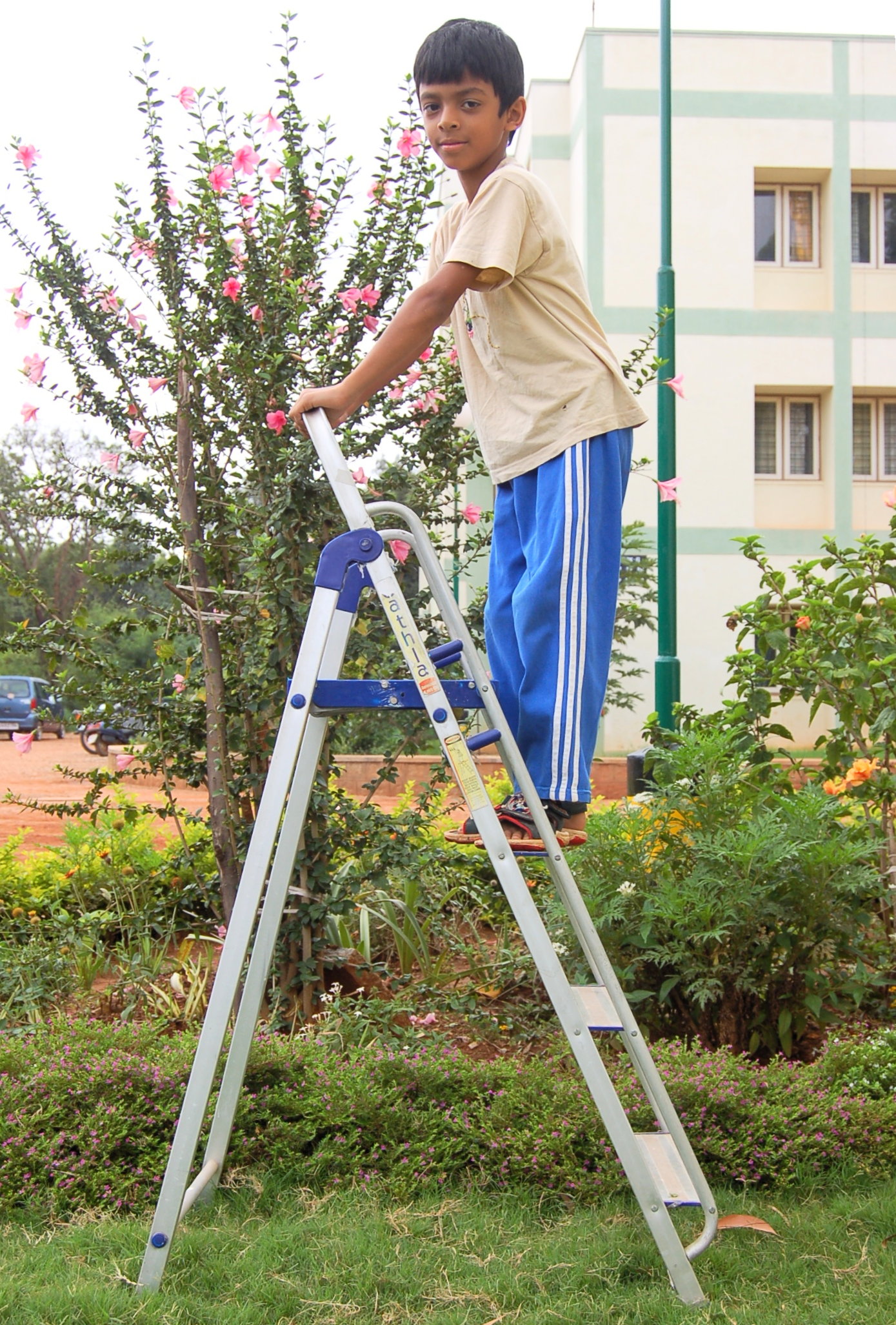
The two-diagonal parts of an A-frame ladder are not two-force bodies and thus the ladder, triangular as it looks, is not a truss. And truss analysis is not appropriate.
A 2D frame is a collection of rigid objects connected by hinges. A special case is a truss, where each bar has exactly two hinges.
One could generalize this definition slightly to include also sliding joints. And one could narrow the definition, to exclude mechanisms, by insisting that the structure be rigid. Being precise about these cases is not important because the analysis methods are the same in all cases.
The overall mechanics recipe applies to frames, of course: a) draw free-body diagrams, b) apply the laws of mechanics to each free-body diagram, and c) solve the mechanics equations for unknowns of interest. For trusses, the free-body diagrams of each bar, with the 3 equilibrium equations (6 in 3D) just yield the “two-force” body result that the bar has equal tensions at the two ends. Because there was no more to learn from the bar free-body diagrams we didn’t even draw them. Instead we used the bar tensions as forces on free-body diagrams of the joints. It’s as if the bars were just a means to mediate action-reaction pairs between joints.
For more general frameworks we have to pay full respect to the free-body diagrams of all of the parts, not just the pins. At least for all of the parts that are not two-force bodies.
Here is the analysis of frameworks recipe:
-
•
Draw free-body diagrams of
-
–
the whole structure; and
-
–
the separate parts of the structure; and
-
–
collections of parts of the structure if such seems likely to be fruitful;
-
–
Use the principle of action and reaction in the free-body diagrams so that one action-reaction pair has only one unknown;
-
–
-
•
For each free-body diagram, write equilibrium conditions (force and moment balance).
-
•
Solve the equilibrium equations for desired unknowns.
For the parts that are not two-force bodies, we will not know the directions of the interaction forces a priori, that’s why the method of joints is not used for frames ††margin: Conversely, we could have analyzed trusses the way we are now going to analyze frames. This seldom-used approach to trusses, the ‘method of bars and pins’, is discussed in box 6.4 on page 6.4. .
Naturally one can be on the look out for shortcuts:
-
•
for any two-force bodies assign an equal-valued tension to each end (thus eliminating any need or use for equilibrium equations for that object)
-
•
consider each pin as part of one of the bodies to which it is connected (i.e., there is no need to draw a separate FBD of the pin).
-
•
To minimize calculation, look for a subset of the equilibrium equations that
-
–
contains your unknowns of interest, and
-
–
has as many unknowns as scalar equations, and
-
–
contains as few equations as possible.
-
–
Our general goal here is to find the reaction forces, the interaction forces and the ‘internal’ forces in the components of a statically determinate structure.
Example: An X structure
Two bars are joined in an ‘X’ by a pin at J. Neither of the bars is a two-force body so a free-body diagram of the ‘joint’ at J, made by cutting and leaving stubs as we did with trusses, has 12 unknown force and moment components.
Instead of drawing free-body diagrams of the connections, our approach here is to draw free-body diagrams of each of the structure’s or machine’s parts. Sometimes, as was the case with trusses, it is also useful to draw a free-body diagram of a whole structure or of some multi-piece part of the structure
Static determinacy
A statically determinate structure has
-
•
a solution for all possible applied loads, and
-
•
only one solution, and
-
•
this solution can be found by using equilibrium equations applied to each of the pieces.
Not all practical structures are statically determinate. Some structures are rigid but redundant, thus precluding finding all unknowns from statics. Some structures cannot carry all loads, but can carry the loads of interest (e.g., a vertical cable that can usefully carry a weight but cannot carry a side load). Nonetheless, for starters here we emphasize determinate structures. The basic counting formula
is necessary for determinacy but does not guarantee determinacy. How to count? Frameworks in 2D have three equilibrium equations for each object that isn’t just a point (in which case there are only two equilibrium equations). There are two unknown force components for every pin connection, whether to the ground or to another piece. And there is one unknown force component for every roller connection whether to the ground or between objects. Applied forces do not count in this determinacy check, even if they are unknown.
Example: ’X’ structure counting
In the ‘X’ structure above we can count as follows.
| number of equations | number of unknowns | |||
So the ‘X’ structure passes the counting test for static determinacy.
Redundant structures
A redundant structure can carry whatever loads it can carry in more than one way. If not also indeterminate, a redundant structure has fewer equilibrium equations than unknown reaction or interaction force components. Finding all the reaction components is only possible if one models the deformation, a topic for more advanced structural mechanics.
Example: Over-braced ‘X’
The structure is evidently redundant. Why? Because it has a bar added to a structure that was already statically determinate. By counting we get
| number of equations | number of unknowns | |||
thus demonstrating redundancy.
Box 6.1 The ‘method of bars and pins’ for trusses
This is an aside for those who wonder why truss analysis seems so different than frame analysis.
Trusses are simple frameworks. So the methods used for more general frameworks should work for trusses. They do. The resulting method, which is essentially never used in such detail, we will call ‘the method of bars and pins’.
In the method of bars and pins you treat a truss like any other structure. You draw a free-body diagram of each part.
One approach: treat the pins as parts. One approach is to draw free-body diagrams of each pin also. You use the principle of action and reaction to relate the forces on the different bars and pins. Then you solve the collection of equilibrium equations.
Consider one joint of a truss where three bars meet at a hinge (pin). Below are free-body diagrams of the three bars and of the pin. Assuming a frictionless round pin at the hinge, all the bar forces on the pin pass through its center.
Thus, in 2D, you get two equilibrium equations for each pin and three for each bar. If you apply the three bar equations to a given bar you find that it obeys the two-force body relations. Namely, the reactions on the two bar ends are equal and opposite and along the connecting points. Now application of the pin equilibrium equations is identical to the joint equations we had previously. Thus, the ‘method of bars and pins’ reduces to the method of joints in the end.
Approach two: draw FBDs of just the bars. Another approach is to associate each pin with one of the bars to which it is attached. Then just think of a truss as bars that are connected with forces and no moments. Draw free-body diagrams of each piece, use the principle of action and reaction, and write the equilibrium equations for each bar. This is the approach that is used in this section for other structures.
If three bars A, B, and C are connected to a pin, consider the pin as part of, say, A. Then consider action-reaction pairs between A and B, and between A and C, but not between B and C. Similarly if there are four or more bars, consider interactions between each bar and the one-bar that has the pin.
Determinate equations. In all cases, if the truss is statically determinate the equilibrium equations generated from the free-body diagrams above will produce a solvable set of linear algebraic equations. But, in all cases above, these will not be the more minimal set of equations we generated in the method of joints in the truss analysis. The methods of this box work, they are just harder to implement.
SAMPLE 6.12
The braced X-frame shown in the figure carries two vertical loads and . Points G and H are directly above points A and B respectively. If , find the tension in the brace CD.
Solution
The brace CD is pinned to the X-frame at C and D. The only loads acting on the brace are at its ends C and D. Therefore, it is a two-force body. Let us assume that the tension in brace is . We need to find under the given loads.
The free-body diagram of the whole frame is shown in fig. 6.87. Since the frame is supported by a hinge at A and a roller at B, there are three scalar support reactions acting on the frame. We can now determine all the three reactions from the static analysis of the frame:
Thus all the reactions are known. Now we can analyze either bar AH or bar BG (the analysis is identical) to determine the tension in the brace. The free-body diagram of bar AH is shown in fig. 6.88. Since we are only interested in , we can carry out moment balance about point E () to give
Thus the tension in the brace is twice the total load on the structure.
Answer:
SAMPLE 6.13
The frame shown in the figure is supported by hinges at both A and B. Bar GE is as long as the base AB and bar BH is pinned to GE at the mid point H. Brace CD is pinned at D, the mid-point of bar BH, and is orthogonal to bar BH.
The load on the structure, , is applied at E, at an angle . Given that , find the forces on the inclined bar BH and the support reactions at A and B.
[Note: Usually, determinate framed structures are made up of overhangs and extensions on a rigid triangle. This structure is an example of a frame that does not contain any rigid triangle.]
Solution
The given structure has hinges at both A and B. Therefore, there are four scalar support reactions, two each at A and B. So, from the free-body diagram of the whole structure, we cannot determine all support reactions. In fact, the free-body diagram of each rod will have more than three unknown forces (you can check this mentally). Thus, we are not likely to find all unknown forces on a bar without analyzing other bars. Since bar CD is a two-force member bar, it only contributes one scalar force, the tension in this rod. Now, there are two unknown scalar forces at each pin joint, A, B, G, and H, and one force at C and D (the same force). Thus we have nine unknown scalar forces. We have three bars AG, GE, and BH, each with three independent scalar equations of static equilibrium. Thus we have nine independent equations in nine unknowns. Therefore, we can solve for all the unknown forces.
Consider the free-body diagram of bar GE. The static equilibrium of this bar requires
| (6.21) |
Thus we have found and but only a relationship between and . Since and are colinear, we cannot solve for them from the static analysis of bar GE alone. Now, let us consider bar AG (or bar BH; does not make a difference). The equilibrium analysis of this bar gives
| (6.22) | |||||
| (6.23) | |||||
| (6.24) |
Since none of these equations contains only one unknown, we cannot solve for these forces from the equilibrium equations of bar AG alone. Note that we have written these equations in terms of , and , thus far, undetermined geometric variables. However, we can easily find them from the given geometry.
Now let us analyze bar BH.
| (6.25) | |||||
| (6.26) | |||||
| (6.27) |
So, now we have seven independent equations, eqns. (6.21)–(6.27), in seven unknowns — , , , , and (we have already solved for and ). We can solve these seven equations on a computer.
Before we go to the computer, let us find the undetermined geometric quantities and . From fig. 6.93, we see that
where , , and . Now, we are ready to solve the seven equations on a computer.
% input given quantities
d = 2; h = 3; F = 1; alpha = pi/3;
% Define other used quantities in the equations
Delta = 3*d^2/(8*h);
h1 = h/2 - Delta;  h2 = h/2 + Delta;
theta = arctan(0.5*d/h);
% Input equations
eqset = { Hx - Gx = F*cos(alpha)
          Ay + RCD*sin(theta) = -F*sin(alpha)
          Ax*h1 - Gx*h2 = 0
          Ax + Gx + RCD*cos(theta) = 0
          By - RCD*sin(theta) = 2*F*sin(alpha)
          Bx - Hx - RCD*cos(theta) = 0
          (Hx+Bx)*h/2 + By*d/4 = -F*d/2*sin(alpha) }

solve eqset for Ax, Ay, Bx, By, Gx, Hx, and RCD
Including the values of and obtained from the first two equations of equilibrium of bar GE, we get the following values for all unknown forces from the computer solution.
Answer:
SAMPLE 6.14
An easy-chair uses a curved frame as shown in the small picture in fig. 6.94. To simplify geometry, we can model the chair with straight bars as shown in the figure. Of special significance is the small pin at E that is rigidly attached to bar CDH and slides with negligible friction on bar ABD (see inset). This pin keeps the chair from collapsing and bears a large load. Assume the pin is away from joint D towards B along bar ABD.
Solution
First, referring to the figures, there is still some geometry needed. We can find and by looking at the position of G relative to H two ways. One is directly from H to G. The other is going from H to E, then E to B, and then B to G. Writing this as a vector equation we get:
The right hand side has all given quantities. Look at this vector equation as two scalar equations. Square the first and add it to the square of the second gives . Applying this to either of the two equations then gives .
Because the chair is supported by a hinge at A and a roller at B, there are three scalar support reactions. So, we can determine them from the static analysis of the whole chair frame. The free-body diagram of the chair is shown in fig. 6.95. The moment and force equilibrium equations give
From the given geometry,
Substituting these dimensions above with their numerical values, we get
The support reactions are thus determined. To find the force on the pin E, we can use either bar ABD or bar CDH. In either case however, we have more unknown forces on the bars than we can determine from the equilibrium equations of that bar alone. So, we will have to use equilibrium of some other bar as well. Note that bar GH is a two-force body. Therefore, the tension in this rod can be shown as a single scalar force . Let us now analyze the equilibrium of bar BGJ since it has only three unknown forces on it (see fig. 6.96). The moment and force equilibrium equations give
Now that we know and , we can analyze bar ABD and determine the rest of the unknown forces on it including the force in the pin E, (see the free-body diagram in fig. 6.97):
From geometry,
Substituting these variables with their numerical values above, we get
Answer:
Check: equilibrium of bar CDH
We can check for consistency by seeing if the equilibrium equations for bar CDH are satisfied, and they are (arithmetic not shown).
| (Checks!) | ||||||
| (Checks!) | ||||||
| (Checks!) |
SAMPLE 6.15
A stack of three cylinders in static equilibrium? Three identical cylinders, each of mass and radius , are stacked such that the top cylinder rests on the lower two cylinders. The two cylinders at the bottom do not touch each other. The coefficient of friction, between the cylinders and between the cylinders and the ground, is . Find the minimum value of so that the three cylinders are in static equilibrium.
Solution
We seek the forces for equilibrium. Knowing the forces, we can find the needed friction coefficient .
The free-body diagrams of the upper cylinder and the lower right cylinder (why the right cylinder? No particular reason.) are shown in fig. 6.99. The contact forces, and , act on the upper cylinder at points E and D, respectively. Each contact force can be thought of as a force normal to the contact surface plus a tangential friction force . From the free-body diagrams, we see that each cylinder is a three-force body. Therefore, all the three forces — the two contact forces and the force of gravity — must be concurrent. This requires, for both cylinders, that the two contact forces must intersect on the vertical line passing through the center of the cylinder (the line of action of the force of gravity). Now, if we consider the free-body diagram of the lower right cylinder, we find that force has to pass through point B since the other two forces intersect at point B. Thus, we know the direction of force . Note that ODB is a straight line.
Let be the angle between the contact force and the normal to the cylinder surface at D. Now, from geometry, . But, . Therefore,
where follows from the fact that C1C2C3 is an equilateral triangle and C3G bisects C1C3C2.
Note that is the friction angle between the surface normal and the friction force. Somewhat surprisingly, this same is the friction angle for both for and for . Now, from fig. 6.100, we see that
But, the force of friction . Therefore,
The friction coefficient must be at least 0.27 if the three cylinders have to be in static equilibrium.
Answer:
Problems for 6.4 Frames
Preparatory Problems
6.4.1 In what way(s) is/are trusses different from more general frames?
6.4.2 Consider a frame made of 3 pieces connected together. Assume that no free-body diagram cut is within a part.
-
(a)
How many different free-body diagrams can you draw?
-
(b)
For each free-body diagram how many independent scalar equations can be extracted from the equilibrium relations?
-
(c)
In total, from all the free-body diagrams, how many independent scalar equations can be extracted from the various equilibrium conditions?
6.4.3 Consider the two-bar frame shown. Choose appropriate coordinate axes. Find
-
(a)
The reaction at D.
-
(b)
The tension in bar DB.
-
(c)
The reaction at A.
-
(d)
The force of DB on ABC.
-
(e)
The moment in ABC
-
•
just (an infinitesimal distance) to the right of A
-
•
just to the left of B
-
•
just to the right of B
-
•
just to the left of C
-
•
6.4.4 Two 1m bars are pinned together, at their middles, at right angles. Find
-
(a)
the reactions at B and D,
-
(b)
the force of BC on AD, &
-
(c)
the moment in AD just above the hinge,
6.4.5 For the structure shown find
-
(a)
the tension in the string
-
(b)
the reaction at A
-
(c)
the moment in ABC just to the right of B
More-Involved Problems
6.4.6 An A-frame aluminum ladder consists of two uniform , sections that are pinned at the top and held from splitting by a massless strut above the slippery floor. An person has climbed halfway up the left side.
-
(a)
Find the reactions (the forces of the ground on the two ladder sections).
-
(b)
Find the force of the left section on the right at the top pin.
-
(c)
Find the tension in the connection strut.
-
(d)
Find the moment in the right leg of the ladder just above the tension strut.
6.4.7 To make a model of a table statically determinate, we assume that leg EA slides easily on the floor. Assume the other leg does not slip. A force acts at at the center of the table. Use and . Find
-
(a)
the reactions at A and B,
-
(b)
the tension in GH,
-
(c)
the moment in IHB just below H.
6.4.8 Another way to make a model of a table statically determinate (see problem 6.105) is to assume that one leg is not braced. Now, neither leg can slip. A force acts at at the center of the table. Use and . Find
-
(a)
the reactions at A and B
-
(b)
the tension in GH
-
(c)
the moment in IHB just below H
6.4.9 For the structure shown find the reaction at A.
6.4.10 The structure consists of two pieces: bar AB and ‘T’ EBCD. They are connected to each other with a hinge at B. They are connected to the ground with hinges at A and E. The force of gravity is negligible. Find
-
(a)
The reaction at A.
-
(b)
The reaction at E.
-
(c)
The moment in BCED just to the left of C.
-
(d)
Why are these forces so big or small? (Your answer should be in words).
6.5 Advanced truss concepts: determinacy
Your first concern when studying trusses is to develop the ability to solve a truss using free-body diagrams and equilibrium equations. You can do this with the method of joints. For some trusses you can use the method of sections as a short cut.
However, not all trusses give a unique solution. In algebra there are equations with non-unique solutions (e.g., ) and sets of equations with no solutions ( and ). We have seen this issue before in the context of static equilibrium of a particle (see box 5.1 on page 5.1). With trusses the issues of existence and uniqueness remain.
Determinate, rigid, and redundant trusses
A truss that yields a solution, and only one solution, to such an analysis for all possible loadings is called statically determinate or just determinate. The braced box supported with one pin joint and one pin on rollers (see fig. 6.109a) is a classic statically determinate truss. A statically determinate truss is rigid and does not have redundant bars.
You should be warned, however: there are other possibilities.
Some trusses are non-rigid, like the one shown in fig. 6.109b, and can not carry arbitrary loads at the joints.
Example: Joint equations and non-rigid structures
Free-body diagrams of joints A and B of fig. 6.109b are shown in fig. 6.110.
The contradiction that is both and implies that the equations of statics have no solution for a horizontal load at joint B.
A non-rigid truss can carry some loads, and you can find the bar tensions using the joint equilibrium equations when these loads are applied. For example, the structure of fig. 6.109b can carry a vertical load at joint B. Engineers sometimes choose to design trusses that are not rigid, the simplest example being a single piece of cable hanging a weight. A more elaborate example is a suspension bridge which, when analyzed as a truss, is not rigid.
A redundant truss has more bars than needed for rigidity. As you can tell from inspection or analysis, the braced square of fig. 6.109a is rigid. Nonetheless engineers will often choose to add extra redundant bracing as in fig. 6.109c for a variety of reasons.
-
•
Redundancy is a safety feature. If one member breaks the whole structure holds up.
-
•
Redundancy can increase a structure’s strength.
-
•
††margin: Tensegrity structures. Notice that you could make the diagonals in fig. 6.109c both sticks and all of the outside square from cables and the truss would still carry all loads. This is the simplest ‘tensegrity’ structure. In a tensegrity structure no more than one bar in compression is connected to any one joint. (See fig. 6.11 for a more elegant example.). The label ‘Tensegrity structure’ was coined by the truss-pre-occupied designer Buckminster Fuller. Fuller is also responsible for re-inventing the “geodesic dome” a type of structure studied previously by Cauchy.
Redundancy can allow tensile bracing. In the structure of fig. 6.109a if the top load was to the left it would put bar BC in compression. Thus bar BC can’t be, say, a cable. But in structure fig. 6.109c both diagonals can be cables and neither need carry compression for any load
.
A property of redundant structures is that you can find more than one set of bar forces that satisfy the equilibrium equations. Even when the loads are all zero, these structures can have non-zero locked-in forces (sometimes called (‘locked-in stress’, or ‘self stress’). In the structure of fig. 6.109c, for example, if one of the diagonals got cool and contracted, both it and the opposite diagonal would be put in tension while the outside was in compression. For structures whose parts are likely to expand or contract, or for which the foundation may shift, this locked-in stress can be a contributor to structural failure. So redundancy is not all good.
Finally, a structure can be both non-rigid and redundant as shown in fig. 6.109d. This structure can’t carry all loads, but the loads it can carry it can carry with various locked in bar forces.
More examples of statically determinate, non-rigid, and redundant trusses are given on pages 6.113 and 6.114.
Note, one of the basic assumptions in elementary truss analysis which we have thus far used without comment is that
motions and deformations of the structure are not taken into account when applying the equilibrium equations.
If a bar is vertical in the drawing, then it is taken as vertical for all joint equilibrium equations.
Example: Hanging rope
For elementary truss analysis, a hanging rope would be taken as hanging vertically even if side loads are applied to its end. This obviously ridiculous assumption manifests itself in truss analysis by the discovery that a hanging rope cannot carry any sideways loads (if it must stay vertical, this is true).
Determining determinacy: counting equations and unknowns
How can you tell if a truss is statically determinate? The only sure test is to write all the joint force-balance equations and see if they have a unique solution for all possible joint loads. Because this is an involved linear algebra calculation (which we skip in this book), it is nice to have shortcuts, even if not totally reliable.
Here are three:
-
•
See, using your intuition, if the structure can deform without any of the bars changing length. You can see that the structures of fig. 6.109b and d can distort. If a structure can distort, it is not rigid and thus is not statically determinate.
-
•
See, using your intuition, if there are any redundant bars. A redundant bar is one that prevents a structural deformation that already is prevented. It is easy to see that the second diagonal in structures of fig. 6.109c and d is clearly redundant so these structures are not statically determinate.
-
•
Count the total number of joint equations, two for each joint. See if this is equal to the number of unknown bar forces and reactions. If not, the structure is not statically determinate.
The counting formula in the third criterion above is:
| (6.28) |
where is the number of joints, including joints at reaction points, is the number of bars, and is the number of reaction components that shows on a free-body diagram of the whole structure (2 from pin joints, 1 from a pin on a roller).
If , the structure is necessarily not rigid because then there are more equations than unknowns
.
For such a structure, there exist some loads for which there is no set of bar forces and reactions that can satisfy the joint equilibrium equations. A structure that is non-redundant and non-rigid always has (see fig. 6.109b).
If , the structure is redundant because there are not as many equations as unknowns; if the equations can be solved, there is more than one combination of forces that solve them. A structure that is rigid and redundant always has (see fig. 6.109c).
But the possibility of structures that are both non-rigid and redundant makes the counting formulas an imperfect way to classify structures.††margin: In the language of mathematics we would say that satisfaction of the counting equation is a necessary condition for static determinacy but it is not sufficient.
Non-rigid redundant structures can have , , or . The redundant non-rigid structure in fig. 6.109d has .
The discussion above can be roughly summarized by this table
(refer to fig. 6.109 for a simple example of
each entry and to pages 6.113
and 6.114 for several more examples).
| Truss Type | Rigid | Non-rigid | ||
|---|---|---|---|---|
| Non-redundant | a) | b) | ||
| (Statically determinate) | ||||
| , | ||||
| Redundant | c) | d) | , | or |
A basic summary is this:
If
-
•
and
-
•
you cannot see any ways the structure can distort, and
-
•
you cannot see any redundant bars
then the truss is likely statically determinate. But the only way you can know for sure is through either a detailed study of the joint equilibrium equations, or familiarity with similar structures.
On the other hand if
-
•
, or
-
•
, or
-
•
you can see a way the structure can distort, or
-
•
you can see one or more redundant bars,
then the truss is not statically determinate.
Example: The classic statically determinate structure
A triangulated truss can be drawn as follows:
-
1.
draw one triangle,
-
2.
then another by adding two bars to an edge,
-
3.
then another by adding two bars to an existent edge
-
4.
and so on, but never adding a triangle by adding just one bar, and
-
5.
you hold this structure in place with a pin at one joint and one pin on roller at another joint
then the structure is statically determinate. Many elementary trusses are of exactly this type. (Note: if you violate the ‘but’ in the 4th rule you can make a truss that looks ‘triangulated’ but is redundant, and therefore not statically determinate.)
Floating trusses
Sometimes one wants to know if a structure is rigid and non-redundant when it is floating unconnected to the ground (but still in 2D, say). For example, a triangle is rigid when floating and a square is not. The truss of fig. 6.111a is rigid as connected but not when floating (fig. 6.111b).A way to find out if a floating structure is rigid is to connect one bar of the truss to the ground by connecting one end of the bar with a pin and the other with a pin on a roller, as in fig. 6.111c. All determinations of rigidity for the floating truss are the same as for a truss grounded this way. The counting formula eqn. 6.28, is reduced to
because this minimal way of holding the structure down uses reaction force components.
The principle of superposition for trusses
Say you have solved a truss with a certain load and have also solved it with a different load. Then if both loads were applied the reactions would be the sums of the previously found reactions and the bar forces would be the sums of the previously found bar forces.
This useful fact follows from the linearity of the equilibrium equations
.
Example: Superposition and a truss
If for the loading (a) you found and for loading (b) you found then for loading (c)
The principle of superposition can only hold if the solution for zero load is zero tension in all the bars. Any truss that only has bars in tension when there is no load does not satisfy the principle of superposition.
Example: Spider web
A network of taut strings is a kind of a truss. So a spider web is a kind of a truss. But a spider web is only a coherent structure if it is kept taut. So there is tension in the strands even when there is no load (from, say the weight of a spider). Thus the principle of superposition does not apply. The tension in a given strand is not the tension due to the spider added to the tension due to an insect.
Box 6.2 Structural rigidity and geometric congruence
This box is only for the curious. It will not help you solve truss homework problems.
In high school geometry one learns to prove that two shapes are congruent (the same shape and size) if they have enough in common. High school geometry proofs are based on triangles. For example one proof, called “side-side-side” (SSS), says that if two triangles have three sides with corresponding lengths then the corresponding angles are also equal.
Now, here, we claim that structures made of triangles tend to be rigid. Is there a relation between the central role of triangles in geometry proofs and their role in structural rigidity? The answer is yes, but more subtly than you may expect.
Consider one triangle. If the lengths are specified it is like three sticks connected with rubber bands (page 6.1). That two different triangles each with the same 3 side lengths are congruent means that one triangle whose side-lengths are given has no choice about its shape. So for one triangle the SSS proof corresponds exactly to structural rigidity.
More generally, imagine looking at a structure and thinking of certain aspects of it as fixed and others as not fixed. For example, think of a collection of bars with the lengths fixed (each bar cannot stretch or shrink) and the angles between them as not-fixed (the angles are flexible). This would be a model, say, of bars connected with pin joints. If one could find a geometry proof that these two structures had identical shapes it would mean that each one of them had no choice about its shape. So a geometry proof of congruency, based on the aspects of a structure that are approximately fixed, is a proof of structural rigidity. This shows that there is a connection between congruence proofs and structural rigidity.
Here’s the subtlety. Neither congruence proofs nor rigidity actually depend essentially on triangles. There are congruence proofs for shapes that do not have any closed triangles, and the related structures are rigid.
In fact, there is a whole arcane mathematics of rigidity. And the things mathematicians have learned about rigidity are incredible.
The case of
Take 3 points on a plane and mark them with dots. Take 3 more points on the plane and mark them with little x’s. Connect each dot with each x. Thats 9 connection lines. In topology-speak they call this set of dots and lines “K three three” (Konnections between three dots and three x’s).
Now think of that criss-crossed drawing as a structure made of sticks connected with hinges at the dots and x’s. Note that, neglecting where the sticks cross but are not connected, there are no closed triangles. Yet, incredibly, this structure is always rigid. Well, almost always. If all 6 points happen to lie on one circle, ellipse, parabola or hyperbola then the structure is not rigid.
Example: Regular hexagon
If you take a regular hexagon made of sticks (length and hinges and brace it with three cross bars (each with length ) you will see that you have K33; every-other corner is a dot and the alternate ones are x’s. But the points on a hexagon are on a circle, so that structure is not rigid.
Example: Triangle with two bars per side
On the other hand, take an equilateral triangle and cut each side in half so you have six bars around the outside (each with length ). Now brace that hexagon (that is shaped like a triangle) with the three triangle altitudes (each with length ) and you again have K33. But this time it’s rigid.
The examples above are used in the text and homework to illustrate structures that don’t lend themselves to the simple joint-by-joint method-of-joints, nor the method of sections. For these trusses the method of joints leads to a set of equations that need to be solved simultaneously.
The mathematical magic goes on.
If you take any dots and any x’s and connect each dot to each x with a rigid rod () you get a rigid structure. Unless all dots happen to lie on a conic section.
The proofs of such rigidity theorems are way over our heads. But you can simply check such structures for rigidity with the computer program developed in section 6.3.
Rigidity and congruence?
So yes, geometric congruence and structural rigidity are the same subject. But that subject does not totally depend on triangles. Triangles just provide the simple examples and what we vaguely think of as the essence of both subjects.
Box 6.3 Rigidity, redundancy, linear algebra and maps
This mathematical aside is only for people who have had a course in linear algebra. For definiteness this discussion is limited to 2D trusses, but the ideas also apply to 3D trusses.
For beginners trusses fall into two types, those that are uniquely solvable (statically determinate) and those that are not. Statically determinate trusses are rigid and non-redundant. However, a truss could be non-rigid and non-redundant, rigid and redundant, or non-rigid and redundant. These four possibilities are shown with a simple example each in fig. 6.109 on page 6.109, as a simple table on page 6.5, and as a big table of examples on pages 6.113 and 6.114.
Another approach is the table in fig. 6.112 which we now proceed to discuss in detail. It is a more abstract mathematical representation of this same set of possibilities. To start with we use the matrix form of the truss joint equations from page 6.19. To make contact with linear algebra here we take the unknowns as with being the unknown tensions and reaction components. The set of lists of all conceivable tensions and reaction forces we call the “vector space” (it is also ).
The possible loads at the joints are written in the column vector (called , for loads, in the numeric set up). The set of all possible loads we call the vector space .
If we use the method of joints we can write two scalar equilibrium equations for each joint. These are linear algebraic equations. Thus we can write them in matrix form as (see eqn. (6.19) on page 6.19),
| (6.29) |
The classification of trusses is really a statement about the solutions of eqn. 6.29. This classification follows, in turn, from the properties of the matrix .
Another point of view is to think of eqn. 6.29 as a function that maps one vector space onto another. For any eqn. 6.29 maps that to some . That is, if one were given all the bar tensions and reactions one could uniquely determine the applied loads from eqn. 6.29. This map, from to we call . We can now discuss each of the truss categorizations in turn, with reference to the table at the end of this box.
The first column of the table corresponds to rigid trusses. These trusses have at least one set of bar forces that can equilibrate any particular load. This means that for every there is some that maps to (whose image is) . In these cases the map is onto. And the column space of is . Thus needs to have at least as many columns as the dimension of which is the number of rows of .
On the other hand if the structure is not rigid there are some loads that cannot be equilibrated by any bar forces. This is the second column of the table. There is at least some with no pre-image . Thus the map T is not onto and the column space of is less than all of .
The first row of the table describes trusses which are not-redundant. Thus, any loads which can be equilibrated can be equilibrated with a unique set of bar tensions and reactions. Thus the columns of are linearly independent and the map is one-to-one. The matrix must have at least as many rows as columns.
If a truss is redundant, as in the second row of the table, then there are various ways to equilibrate loads which can be carried. Points in in the image of have non-unique pre-images, is not one to one, and the columns of A are linearly dependent. We can now look at the four entries in the table. The top left case is the statically determinate case where the structure is rigid and non-redundant. The map is one to one and onto, , and the matrix is square and non-singular.
The bottom left case corresponds to a truss that is rigid and redundant. The map is onto but not one to one. The columns of are linearly dependent and it has more columns than rows (it is wide).
The top right case is not rigid and not redundant. Some loads cannot be equilibrated and those that can be are equilibrated uniquely. is one to one but not onto. The columns of are linearly independent but they do not span . The matrix has more rows than columns and is thus tall.
The bottom right case is the most perverse. The structure is not rigid but is redundant. Not all loads can be equilibrated but those that can be equilibrated are equilibrated non-uniquely. The matrix could have any shape but its columns are linearly dependent and do not span . The map T is neither one to one nor onto.
SAMPLE 6.16
An indeterminate truss: For the truss shown in the figure, find all support reactions.
Solution The free-body diagram of the truss is shown in Fig. 6.116. We need to find the support reactions , and .
The and components of the force equilibrium, , give
| (6.30) | |||||
| (6.31) |
Now we apply moment balance about point A, . Let A be the origin of our -coordinate system (so that we can write , etc.).
where,
Adding them together and dotting with we get
| (6.32) | |||||
We have three equations (6.30–6.32) containing four unknowns , , , and . So, we cannot solve for the unknowns uniquely. This was expected as the truss is indeterminate. However, if we assume a value for one of the unknowns, we can solve for the rest in terms of the assumed one. For example, let . For simplicity let the right hand sides of eqns. (6.30, 6.31, and 6.32) be , , and (computed values), respectively. Then, we get . The equilibrium is satisfied for any value of . Thus there are infinite number of solutions! This is true for all indeterminate systems. However, when deformations of structures are taken into account (extra constraint equations), then solutions do turn out to be unique. You will learn about such things in courses dealing with strength of materials.
Problems for 6.5 Advanced truss analysis: determinacy, rigidity, and redundancy
Preparatory Problems
6.5.1 Define these terms
-
(a)
statically determinate
-
(b)
rigid and non-rigid
-
(c)
redundant and non-redundant
6.5.2 For each set of conditions below, find 2 trusses both of which fit the description
-
(a)
rigid and non-redundant
-
(b)
rigid and redundant
-
(c)
not rigid and not redundant
-
(d)
not rigid and redundant
6.5.3 In 2D trusses we used the formula . With what formula do we replace this for 3D trusses? Explain why.
6.5.4 For the 3D method of joints, for a whole truss how many independent scalar equilibrium equations can one write?
6.5.5 For one section cut in 3D how many bar tensions can you hope to find?
6.5.6 For a 3D truss that is rigid when not grounded, how many independent reaction components do you need to make it a statically determinate structure for any loading?
More-Involved Problems
6.5.7 For the following structures find at least 2 different sets of bar forces that can equilibrate the applied load shown.
-
(a)
Two bars in a line with a force in the same line.
-
(b)
A square with two diagonal braces.
6.5.8 For the structures and loading shown show that there is no set of bar forces for which equilibrium is possible (at least with the geometry shown). All of these structures are not rigid, they require either infinite bar forces or some (or a lot of) deformation to withstand the load applied
-
(a)
Two bars in a straight line.
-
(b)
A square without a diagonal.
-
(c)
A regular hexagon with three diameters. [This problem is hard and might best be answered using linear algebra methods on the matrix form of the system of equilibrium equations.]
6.5.9 For each of the structures below and the shown loading
answer these questions:
i) Does a set of equilibrium bar forces and ground
reactions exist?
ii) If so, find one such set.
iii) Are the solutions, if they exist, unique?
iv) If not find at least two solutions.
v) Is the structure rigid?
vi) If not, how can it deform?
-
(a)
One hanging rod
-
(b)
A braced pole
-
(c)
A tower
-
(d)
Two bars holding a vertical load. Comment in your answers how they change in the limit .
-
(e)
A regular hexagon with three diagonals (this is a hard problem).
6.5.10 Use your program from problem 6.78 to analyze each pair of structures shown. In each case the output of your program should be radically different for the right structure than for the superficially similar structure on the left. i) Describe the difference in your computer program behavior, ii) As well as you can, explain what it is about the structures that causes this difference in computer behavior.