
Team
Buggy
Competition
Sponsors
Introduction

Suspension was deemed unnecessary or overlooked in last year's buggy, but this year there are several reasons that we have decided to include it.
1. Course traversing:
Last year's buggy was very good at overcoming obstacles that caused the chassis to twist. It was not very good at accommodating bumps that affect both sides of the buggy, or ones that caused it to become airborne. Unfortunately not much of the course was twisting type bumps. This caused the buggy to fail from overloading a frame member during a large bump situation. The design of last year's buggy was partly at fault due to the fact that it was not designed with dynamic loads in mind. Add this miscalculation to a lack of suspension which forced the frame to endure all of the loads of impact directly. The suspension system will also help us keep wheels on the ground during more of the course than an un-suspended one. This helps us steer and put power down to the ground. Pedaling and turning are more effective when the wheels are on the ground.
2. Load Paths:
The load paths of a suspended frame are easy to modify. By moving pivots and frame mounts, all of the loads encountered can be directed into nodes specifically designed to accommodate such forces. The introduction of a set of springs into the system also helps to reduce impulse forces, and turn them into easy to calculate force vectors. Granted, there are many springs in our system (tires, ground, beams bending) but the magnitude of the suspension almost totally overrides all of the other spring systems when designed correctly.
3. Driver Comfort:
The last but possibly most important goal of the suspension is allowing the rider to exert as much energy as possibly to forward motion. If they are not comfortable while pedaling due to position or consistent battering by bump loads, they will not be as efficient. The less efficient the driver is, the slower the buggy goes around the course.
Relevant Terms
Spring/damper: a spring and damper system with spring constant k and damping coefficient c. They will probably be provided by a mountain bike type system with either air or coil springing and oil damping.
Wheel travel: the vertical distance that the wheel moves because of suspension movement.
Spring rate: the spring constant k of the spring
A arm: an a-shaped arm comprised of two tubes with three pivots. Two of the pivots are mounted to the frame, and the third to the upright.
Upright: the vertical member between the upper and lower a-arms that allows the wheels to be attached to the suspension system
Motion ratio: the ratio of wheel travel to spring/damper travel
Push link: a solid link between the lower a-arm and a rocker so that force from the wheel is directed towards a spring/damper - in compression
Pull link: a solid link between the upper a-arm and a rocker so that force from the wheel is directed towards a spring/damper - in tension
Rocker: a device that takes a force from one direction and re-directs it to another direction. This is usually accomplished through a pivoting or rocking mechanism.
Camber: the inward or outward tilt of the top of the wheels when viewed from the front of the buggy. The tops of the wheels facing inwards is negative camber, outwards is positive camber. / \ is negative camber, \ / is positive camber. Measured in degrees, minutes, and seconds.
Caster: when viewed from the side, caster is the tilt of the steering axis. When looking at the left front wheel of the buggy, if the top of the upright is behind the bottom of the upright, there is negative caster. If it is in front, there is positive caster. So / would be negative caster and \ would be positive caster. Measured in degrees, minutes, and seconds.
Toe in: when the front of a set of wheels point inward towards one another. Measured in degrees, minutes, and seconds.
Toe out: when the front of a set of wheels point outward away from one another. Measured in degrees, minutes, and seconds.
Static ride height: the height of the frame above the ground that the buggy will sit at when motionless and loaded with all drivers and accessories.
Compression travel: when the suspension compresses from static ride height and the frame gets closer to the ground
Droop travel: when the suspension extends from static ride height and the frame gets farther from the ground
Bottoming: when the suspension cannot compress any farther
Top out: when the suspension cannot extend any farther
Roll: the twist of the chassis measured in relation to the ground. The frame has 0 degrees of roll when it is standing still, but if it is cornering or on a sidehill the frame will twist in relation to the ground due to the suspension compressing unevenly side to side. Measured in degrees, minutes, and seconds.
Design Notes
A-arms
An A-arm suspension was chosen because it has proven performance, fits the design of our frame well, and is well within our power to construct. Several other types of suspensions were initially examined, but none were as easy to implement with results as predictable as the A-rms. The forces are easily brought into nodes, and the springs can be attached with a motion ratio to get the proper spring rates and wheel travel.
Spring Rates
Spring rates for this year's moonbuggy were designed to support the vehicle under the worst circumstances. Two sets of calculations were performed, one taking into account six inches of suspension travel, and the other with eight inches of travel. In order to keep the vehicle stable under all conditions I assumed a worst case scenario and chose spring rates to keep the buggy from bottoming. Brett and I decided that dropping the buggy off of a two foot ledge would adequately simulate the best of air time on the course. With six inches of travel, the average spring rate came to 166lb/in and the figure for eight inches of travel is 99lb/in. These are only average figures, we know the actual spring rates will probably not be linear. Therefore we will try to use these figures as our average spring rate, not a constant rate at all points.
Motion Ratio Suspension
Once we decided to use rocker geometry, we needed to decide how to actuate the rocker to best suit our purposes. The two most common methods of rocker actuation are push links and pull links. Push links are a bar that is attached to the lower A-arm of the suspension system that runs upward to the rocker assembly to actuate the spring and damper. Pull links run from the end of the upper A-arm to near the bottom of the frame where they attach to a rocker that compresses the spring and damper.
Pull links have the advantage of being purely and tension and can be made light because there is little chance of them being put into a buckling load. There is not much space to mount the rockers on our frame if we want to keep ground clearance in check, but it could be handled with some innovative bracketry. Since the pull link mounts to the upper a-arm, adjustments become more difficult. Camber and caster are conventionally adjusted at the upper A-arm because it is most accessible and sees less loads than the lower a-arm. Adjusting camber usually requires an adjustment of caster and vice versa. Pull rods are used to set the bump and ride heights of the vehicle. This adjustment would then require adjustments of camber and caster as well, eventually producing an iterative approach to adjustment instead of one that can be calculated.
Push rods on the other hand mount to the lower A-arm so adjustments in ride height can be made independent of camber and caster adjustments. Using a push rod setup allows us to put the rockers at the top rail of the frame and mount the spring/dampers vertically to the node at the base of the frame. This way all forces will be at nodes and our frame will be able to handle the loads easily. They must be built slightly beefier than pull links because they are essentially columns in buckling as opposed to tension. In our case, I believe that this will have minimal impact on the overall performance of the buggy considering the total weight of the system.
Suspension Geometry
The suspension geometry for the front suspension has been determined from the following parameters:
- 14" minimum frame height at ride height
- 5" distance from outside of wheel to closest point where a-arms may attach
- 10" outside-outside frame width at top of frame
- 6" frame height
- 29" outside diameter tires (note that this is no longer accurate, we've moved to 26" diameter tires but our ride height is still above the legal minimum)
From these parameters, the front suspension was designed. This design is independent of spring rates, but they will obviously affect its performance. The following goals were set forth for designing the setup:
- Maintain negative outside wheel camber in turns
- Produce positive camber on inside wheel in turns
- Minimize camber change in bump
- Create a suspension that handles well in bump and roll
Meeting these constraints was difficult for several reasons. Overall our A-arm dimensions are very short to maintain camber change during 8" of travel. Frame dimensions are fairly static and cannot be changed much at all. And to add into the pot the ability to maintain control during cornering made this very challenging. I created over 45 iterations of this front suspension setup using Mitchell, a vehicle simulation program. Below are the parameters that I would like to see for our front suspension system:
Static camber: 0 degrees
Static caster: -4.645 degrees
The following coordinates are based on an origin of coordinates at the center of the frame, on the ground, in line with the axle of the vehicle.
This setup gives the following results from simulated testing:
With 4 degrees of chassis roll and 3 degrees of steering input:
Outside camber = -1.013 | Inside camber = .715
With 4 degrees of chassis roll and 6 degrees of steering input:
Outside camber = -4.834 | Inside camber = 4.492
At full bottoming (-5.5")
Camber = -6.678 degrees
At full top out (+2.5")
Camber = 1.931
This is not a truly ideal geometry due to design restraints, but it roughly fits the design constraints. The rounded profile of our tires is less sensitive to camber change than normal flat treaded street tires so as long as we have the correct sign of camber (positive or negative) we should be ok, especially considering the high lean angles that most mountain bikes can operate in. Compared to my first iteration (with the frame 1" narrower and 1" more scrub radius) this setup is less stable in camber. This is due to the change in dimensions of the lower a-arm in relation to the upper. I have done a lot of optimization but I think that this is as close as I can get to ideal at this point.
The rear suspension has similar, but not identical geometry to the front. The wheel offset and frame designs are the same, but we cannot use caster angle to create negative camber while cornering due to the lack of steering at the rear wheels. That will give us more trouble maintaining negative camber on outside wheels and transitioning to positive camber on the inside wheel, but we can minimize the effect to some degree. Although it will also give us more negative camber in bump as well as minimizing the positive camber in roll I don't think it will affect our handling too much as the bike tires are fairly round, and as long as we are not too far positive there should be no negative effects. I also expect there to be about 1 degree more negative static camber in the rear to combat the outside wheel positive camber in roll. One possible advantage to this setup, is that if the heavier person ends up being in front of the buggy, the positive camber on the inside rear wheel could contribute to more neutral handling with less understeer in moderate speed corners.
This setup was designed with 8 inches of total travel in mind (5.5" compression, 2.5" droop) but it could easily be modified for 6 inches if so desired. The changes would actually only take place in the rockers and motion ratio, not the geometry of the a-arms. As long as static ride height is maintained, the suspension geometry will perform as expected.
Suspension Materials
Once the dimensions of the a-arms and related components were determined, the materials to construct them had to be chosen. The design of these parts was based on the same force analysis used to design the uprights. The loading conditions were the maximum that we would EVER encounter with the buggy. A factor of safety was then added to the max load to make sure the major suspension components would not fail. In fact, based on the loading, it appears that our wheels will buckle well before any of the suspension components come close to failure. This is good, as the wheels are the known weak link, and replacing them is both easier and less damaging than replacing major suspension parts. The loads were based on a moonbuggy of 100lbs with two 150 lb riders, cornering and braking at 1.5g's on two wheels. From these numbers, the loads were distributed into the upper and lower a-arms of the suspension based on geometry of the uprights that attach the wheels to the rest of the suspension. The loads in the a-arms were then divided into tension and buckling loads in the two tubes of the arm with force triangles. The loads were then translated into tubing sizes required to prevent buckling, even during reverse loading conditions. The same numbers were used to pick rod end sizes for the ends of the a-arms. Static weight plus 3-g bump loads were used to calculate the push link and rocker material sizes so that they too would not fail. The push links were items in buckling, so that was the calculation that was of interest. Final dimension for the suspension components are as follows:
Upper a-arms: 5/8" .049 cro-mo tubing
Lower a-arms: 1" .035 cro-mo tubing
Push links: 5/8" .049 cro-mo tubing
The rod ends for the upper and lower a-arms were chosen from the available catalogs to accommodate the indicated loads on the a-arms without failure. The rod ends will never see loads close to their rated maximums as indicated above, but the added strength will give us much greater fatigue resistance and durability.
Fabrication Notes
The 8 A-arms were made entirely from 4130 steel. Inserts (to allow the rod ends to be screwed in) were made first out of appropriately sized solid rod stock. Each insert was first cut to length (about 1 in. for the top A-arms and about 2 in. for the bottom A-arms) and then drilled and tapped so that the rod end could thread in. Stock for the A-arms was then cut and mitered so that where the two bars came together they met and surrounded the insert with as few gaps as possible. The assembly was then laid against the frame to make sure the angle between the two bars was correct and the three pieces were welded together. After the weld cooled, the thread for the rod end was re-tapped to remove any oxidation or warping of the metal caused by the welding process.
In the interest of time, we didn't make any jigs, all of the alignment was done by eye with some help from marks on the frame and a T-square. To save money, the A-arm attachment points on the frame were constructed without rod ends. This eliminated the need for 16 additional rod ends (at about $8 each, that's $126). We drilled a 7/16" hole down the length of a section of solid rod stock slightly less than 1.5" long. Then 7/16" OD (5/16" ID) brass shoulder bushings were pressed into either end and these cylinders were then mounted to the previously constructed A-arm attahment points on the frame using a 5/16" rod. Both cylinders for one A-arm were put in at the same time so that the entire A-arm could be aligned properly. The A-arm tubes were then mitered to butt against the sides of the two cylinders and were welded in place. The welding generally ruined the brass bushings, so they were then popped out using a special tool made for the purpose and replaced.
Performance
It was the general consensus that our suspension was one of the best at the competition if not the best there. Although we never had time for a proper suspension adjustment session, it still worked wonderfully. Better tuning of camber and toe would have resulted in easier turning and less rolling friction. We had serious concerns about our lack of anti-roll, however body roll during cornering was very minimal.
The suspension achieved all of the goals we set for it. The moonbuggy rarely, if ever, left the ground while running the course meaning traction was available for accelleration or turning at all times. Impulse forces caused by bumps were significantly reduced giving the riders a smoother ride and allowing for a lighter frame. As proof of all of these facts, the moonbuggy easily goes up and down street curbs at speed, and with practice, an experienced rider can take it down stairs.
Lessons Learned
I would recommend the overall suspension strategy to future teams: four-wheel independent, A-arm suspension actuated by rockers and pushrods with mountain bike shocks providing the spring and damper package. If more money is available, I think looking into rod ends at the frame and a spherical bearing at the upright would make the suspension lighter and more adjustable. The rod ends could be mounted inside the frame tubes resulting in a more idealized truss (and would make the welder much happier!).
Further analysis should be done on the A-arm tubes to make them lighter. For example, the forward tube is in tension only, meaning it can be thinner than the rearward tube, which is in compression. Also, due to a mistake on Brett's part, the top rear A-arms were made of 5/8" x .035 tubing instead of the 5/8" x .049 tubing that was called for. In spite of this error, the rear A-arms never showed any signs of failure.
Along these lines, some sort of bumper should be considered to protect the forward tubes of the front A-arms in the event of a colision. A colision with a railing after the competition put a dent in the right front A-arm. Even some pipe insulation like that used to pad the seat back would provide some protection and would be very easy to implement.
The camber adjustment required removing the upright from the A-arms and threading the rod end in or out. This was actually quite difficult and therefore meant that we did it less. If the suspension adjustments were made easier, we would use them more.
Rockers
Using a rocker arm allows us to get 6 to 8 inches of wheel travel out of a shock with 2 to 3 inches of travel. The front rocker set mounts to the top members of the frame between the A-arm attachment points. The shock mounts between the rocker and the bottom frame member as shown in the cross-sectional view below.
In the rear, the rockers are mounted to the frame in a similar manner behind the rider. We considered flaring the frame behind the rider to make the rockers closer to the wheels, however we decided this would not benefit us. The frame simply extends four inches behind the rider so that the rockers may mount there. This is necessary because in the rear of the buggy, the seat interferes with conventional rocker placement.
Design Notes
To calculate the dimensions of the rocker, we assumed that from static ride height, we wanted at least 6 inches of travel upwards, and also at least 2 inches of droop. Calculation of the rocker geometry went as follows:
Finding a relationship between q1 and q3:
Nonlinear equation:
Using Matlab, it was possible to solve this transcendental equation for theta3. Once the value for theta3 (see diagram) was obtained, it was possible to find the vector R50 (see diagram), the distance from the end of the horizontal rocker piece to the shock attachment point. If this is subtracted from the initial R50 (initial shock position), the shock compression is obtained. By assuming that we will get a shock with 2.75 inches of travel, it was possible to find the necessary dimensions of the rocker arm and the initial angle (at ride height) The vertical rocker piece must make with the horizontal.
As you can see in the calculations, I assumed that the vertical and horizontal rocker pieces would be at right angles to each other. This does not necessarily have to be the case, and it would take further analysis or experimentation to understand the effects of varying that angle. A benefit of decreasing the angle in between the rocker arms is that this would reduce the overall height of the arms and thus help clearance with the rider's legs.
The output of the Matlab program is as follows:
for a vertical rocker piece of length:
4.6000 in
and a horizontal rocker piece of length:
3.00 in
and the initial angle that the vertical rocker piece makes with the horizontal is:
30 deg
the resulting shock travel is:
2.7589 in
the length of the pushrod must be:
11.5391 in
the length of the shock at ride height must be:
9.2832 in
the vertical rocker piece travels through an angle of:
-56.0284 deg
This rocker geometry was chosen because it is:
- Compact , but not too small as to be in obvious danger of breaking.
- Gives the necessary travel without requiring too small of an initial angle.
Final Rocker Design
Front Rockers
While the mathematics gave us a good idea of what the dimensions of the rockers had to be, we were still concerned with the general shape of the rockers. We needed to address clearance issues with the frame and shock, and we also wanted to check that we really would get the necessary travel out of the design. Therefore, by using the Matlab results as a guide, we drew a model of the rocker on paper which would incorporate both shape requirements, namely clearing the top tube of the frame, and also having the required dimensions to give us our desired travel. Using a large wooden board, we created a mockup of the suspension system by drawing, to scale, all of the suspension components. By cutting out our initial drawing of the rocker and securing it to the wooden board using a pin placed through the pivot point, we had an accurate picture of the suspension system at ride height.
To assess the rocker's performance, we then manipulated the entire system as if the suspension was compressing. We raise each a-arm individually, making sure that we rotated it about the correct point and maintained all distances that were fixed. By tilting the rocker model about its pivot point, we were able to measure how far the shock end of the rocker moved relative to its initial point. On the first try, the rocker compressed the shock two inches when the suspension went through seven inches of travel. This is exactly what we wanted, based on using two inches of the shock's travel for compression and .75 inches for droop.
Rear Rockers
The design of the rear rockers was complicated by the fact that, unlike the front rockers, the rear rocker's motion is not in plane with the wheel's vertical travel. This is a result of the placement of the rockers behind the rider to avoid interference with the seat. One result of this complication was that we were unable to utilize our "suspension board" to check the rear rocker's performance. Also, the mathematical model used for the front was not entirely applicable because of it two-dimensional nature.
The main challenge in designing the rocker was incorporating size and position constraints while still having the rocker give the necessary wheel travel. We wanted the pushrod to remain, as much as possible, in plane with the shock during most of the travel. This would ensure that the pushrod, rocker, and shock were only in tension and compression throughout the suspension travel, and no other loads were transmitted.
We began design of the rear rockers once the rear a-arms had been completed so that we could use the actual frame for figuring out the necessary dimensions. In essence, the buggy itself served the same function that the 'suspension board' used for the front did. By first fixing the position of the attachment points of the pushrod on the bottom a-arm, the rocker pivot point, and the shock attachment point on the frame, the shape of the rocker became the lone variable which would determine the suspension travel. The locations of these other points were determined based on the needs outlined above, namely space considerations and the goal to have the pushrod remain as in plane as possible with the shock. Initially, we used the front rocker design as a model for the back, to give us a starting point. Right away we realized that the rear rockers must be significantly smaller than the front ones. When the rear suspension was compressed, using the front rocker resulted in small amounts of shock travel. For example, if the wheel hit a bump and needed to compress six inches, which is near the maximum compression travel we wanted, the shock would only compress an inch or so. This means that the majority of the shock's travel, 2.75 inches, would never be used, and we would be wasting the ride quality and suspension benefits of the long travel shocks.
The rear rocker must be smaller because of its tilted orientation. In the front, the wheel moves up and down, and this motion is transmitted through the pushrod to the rocker. In the rear, the wheels are still constrained to move only up and down, but the pushrods are at an angle. This means that a smaller component of the vertical motion is transmitted to the rockers in the rear because some of the motion is sideways. Thus, a rear rocker is seeing less motion than a front one for the same amount of wheel travel, and therefore it can be smaller.
Fabrication Notes
 The rockers were made using a CNC mill. By utilizing this technology, it
was possible to make the rockers both lightweight and have the complex geometry
necessary for the confined space requirements. A welded piece of metal may have
been able to accomplish the same task, but the CNC allowed us to use aluminum and
create an elegant solution to complex packaging constraints.
The rockers were made using a CNC mill. By utilizing this technology, it
was possible to make the rockers both lightweight and have the complex geometry
necessary for the confined space requirements. A welded piece of metal may have
been able to accomplish the same task, but the CNC allowed us to use aluminum and
create an elegant solution to complex packaging constraints.The first design of the rocker included a pocket cut out from the middle to reduce weight. After its completion, however, we recognized that the part had enough material to allow for the complete removal of the pocket material. This dramatically reduced the weight of the rockers.
 I highly recommend using the S-24 (or in the future, the Okuma) CNC mills
for this application. It proved to be more reliable than the Bridgeport mill and
gave more repeatable results.
I highly recommend using the S-24 (or in the future, the Okuma) CNC mills
for this application. It proved to be more reliable than the Bridgeport mill and
gave more repeatable results.
Once the CNC programs were completed, which took a few days each (front/rear) to complete, it took about a day to set up and machine each rocker.
Performance / Lessons Learned
The rockers worked out beautifully on the buggy. They allowed for the inboard mounting of the suspension and smooth, progressive suspension travel. They were also strong enough and do not show any signs of wear or cracking.
In the future, the rockers could be made lighter if some stress analysis is performed. The obviously weakest parts of the rocker were the attachment points. These highly loaded points would probably fail before any other part of the rocker due to bearing stress or tearout. These points were also the thinnest parts of the rocker. This leads me to believe that more material could be removed from the rest of the rocker with no adverse effects
The main lesson learned during this process is that one should always try different approaches to solving a problem. When first presented with this problem, I was amazed at the complexity of the geometry involved and it took a long time to create a viable mathematical model. This experience was very valuable in that it improved my analytical skills and helped me to understand how exactly this system was operating, i.e. what the pivot points were, and how all the pieces moved. After this hard process, however, the alternate method of creating physical models ultimately gave us the final product, and was much easier and quicker to do. While this may not always be possible, it shows that approaching a problem from different angles can be very beneficial.
Shocks
The Moonbuggy is fitted with four Fox Shox ( http://www.foxracingshox.com ) Vanilla RC coil-over-oil spring and damper units. Each has 2.75 inches of travel and is 8.75 inches long in its fully extended position. We decided to use rear mountain bike shocks for several reasons. A decent sized market already exists for their production and so they are readily available from several quality manufacturers at a reasonable cost. Furthermore, they are designed to operate under similar conditions, experiencing nearly identical motion ratios and spring rates. They are on the small end of the shock absorber market (compared with ATV's, snowmobiles and other suspended, similarly-sized vehicles) meaning that they will better fit our volume and weight limitations. Fox Shox was the first manufacturer we contacted in our search for these parts. They could send us the items we wanted in a reasonable amount of time and gave us their OEM prices - about 2/3 off the retail price ($349.00), a substantial discount - so we decided to buy from them.
Fox offers two product lines of rear mountain bike shocks:
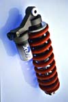 1. The Vanillas are oil damped and use coil springs. The Vanilla R has an
adjustment knob to allow the "R"ebound damping to be adjusted. The Vanilla RC has
two knobs, a "R"ed knob adjusts the "R"ebound damping (just like the Vanilla R) and
a blue knob adjusts the compression damping. Jeff Curtis from FSAE told us that
the blue knob is a true compression adjustment, but that in spite of its
designation, the red knob affects both rebound and compression. Springs are sold
for the 2.75" Vanilla RC in 50 lb/in increments from 300 lb/in to 1200 lb/in.
1. The Vanillas are oil damped and use coil springs. The Vanilla R has an
adjustment knob to allow the "R"ebound damping to be adjusted. The Vanilla RC has
two knobs, a "R"ed knob adjusts the "R"ebound damping (just like the Vanilla R) and
a blue knob adjusts the compression damping. Jeff Curtis from FSAE told us that
the blue knob is a true compression adjustment, but that in spite of its
designation, the red knob affects both rebound and compression. Springs are sold
for the 2.75" Vanilla RC in 50 lb/in increments from 300 lb/in to 1200 lb/in.
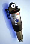 2. The Floats are oil damped and have an air spring. The "R" and "RC" suffixes
apply to the line of Floats as well. Because these shocks employ an air spring,
infinite adjustment of the spring rate is possible. A valve on the shock allows
pressure to be released or added using a pump (I assume a regular bicycle pump will
work although I'm not certain).
2. The Floats are oil damped and have an air spring. The "R" and "RC" suffixes
apply to the line of Floats as well. Because these shocks employ an air spring,
infinite adjustment of the spring rate is possible. A valve on the shock allows
pressure to be released or added using a pump (I assume a regular bicycle pump will
work although I'm not certain).In order to maintain a reasonable motion ratio we wanted the full 2.75" of travel (the largest shock Fox makes) and of the two lines (Vanilla and Float) and two damping options (R and RC) only the Vanilla RC is available in this size.
Spring Rate Calculation:
The spring rate for the coil spring was calculated based on the calculated spring rate for the entire vehicle (see suspension design notes for how this was calculated).
Kvehicle = 150 lb/in => This means that if a 150 lb weight is placed on the assembled Moonbuggy, the frame will droop 1 inch.
Given this, the spring rate for each shock depends on the motion ratio.
Therefore, the spring rate of each coil spring should be:
Therefore we ordered the 300 lb/in springs for all four shocks.
Fabrication Notes
The only work that was done on the shocks was the implanting of spherical bearings, one at each end. At the factory, the aluminum is machined to an ID of .593"-.594" and then a steel sleeve (called a "DU", I don't know what "DU" stands for) is pressed into the hole, giving it a new ID of .5 inches. Then two aluminum reducers are slid into the steel sleeve, one from each side. These aluminum reducers fit loosely in their steel sleeve and act as a bushing to allow the shock to pivot. When I ordered the shocks from Fox, I specified that they be manufactured and assembled without the reducers and DU's installed in the mounting holes. Apparently, many FSAE teams purchase Vanilla RC's from Fox and have the same problem that we had, namely no spherical bearings exist with an OD of .594 inches. Rumors were circulating that Aurora was going to start a line of spherical bearings just for this purpose, however at the time of the construction, the representative knew nothing of any plans to release bearings this size. Spherical bearings are readily available from several manufacturers with an OD of .625", a scarce .030" too large. I was told by Mike Mooneyham at Fox that there is an internal mechanism related to one of the damping adjustment knobs that passes "very close" to the wall of this hole and therefore we should not attempt to enlarge it for fear of damaging the mechanism. I therefore consulted with the folks at National Rod End (http://www.nationalrodends.com) and decided that the .625" OD spherical bearings (Mfg. No. WSSB4, $8.80 retail) had a thick enough wall that .015" of material could safely be removed from the outside of the bearing without structurally compromising thereby reducing the diameter by .030" so they could be pressed into the shocks.
This worked surprisingly well. Five to ten minutes on a grinder and a bearing could be reduced to the proper size with encouraging accuracy. It helped that the bearings were not required to be perfectly round, that's why we have them is to allow misalignment, they were simply required to press into the shock and stay there. This they did very easily and securely and we haven't had any troubles from them. Of course any procedure that eliminates the need to grind down the diameter of the spherical bearings would be more desirable, however, in spite of its lack of sophistication, I would recommend this method for future buggies.
Performance
Although we didn't have time to fully tune the preload and damping adjustments the shocks still performed very well. The front shocks sagged quite a bit under the rider's weight and this makes me think that some heavier springs might be needed. Also, after coming through a rough section of the course (or going down a curb) the rear end of the buggy bounces for some time making me think the damping in the rear needs to be increased. The shocks show no signs of wear or of failure.
Lessons Learned
I would highly recommend two experiments be done to test the suspension's use of the full shock travel. The first test is to simply remove the shocks from the buggy (with the buggy on a stand) and then actuate the wheels up and down. Measure the motion of the rocker to verify that the assembled suspension actually compresses the shock 2.75" for ~7" of wheel travel as it was designed to do. Although the calculations were performed to ensure this would be the case, the fabrication was rushed and the finished buggy might not perform the way it was designed. Next, a test should be performed to ensure that the full 2.75" is being used while riding. The rubber bumper on the shock piston rod can be slid all the way down against the shock body. Then take the buggy out for a ride that is typical of a "rough" course. When you return, look how far the bumper has been pushed up the piston rod. If it has been pushed only a very little bit, less preload is needed. If it has been pushed all the way to the top, this means the shock has bottomed during the run and the spring should be preloaded more.
Although I'm not sure of their reliability because it is a comparatively new technology, air shocks (Float RC's) should be considered for future years. Admittedly they don't look as cool, but the advantage of infinite spring rate adjustment capability might outweigh this advantage. If the suspension is designed specifically for a particular weight spring and careful attention is paid to fabricating it correctly and to spec, perhaps coil springs could be made to work properly, however, the infinite adjustability is a huge benefit… small manufacturing inconsistencies can be made up for and unexpected dynamic behavior can be tweaked without the added time, cost and inconvenience of ordering new springs... which at best only come in 50 lb/in increments.
The largest Float RC has only 2.0 inches of travel, meaning that if they are considered, some investigation will need to be done into the reduction in damping performance with the larger motion ratio, or the total suspension travel will need to be reduced. Perhaps the larger motion ratio is perfectly acceptable in which case using a smaller shock would be fine and have the added benefit of being lighter weight.
Uprights
Fabrication Notes
Performance
Lessons Learned