
Team
Buggy
Competition
Sponsors
Introduction

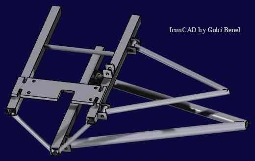
We started designing this buggy from the frame up. There was much discussion about whether to use the single beam frame, similar to other schools' buggies, or to use a completely trussed form similar to our last year's buggy. We finally decided to use the beam frame because of its versatility in designing other components such as suspension and steering. But we would make this beam actually a trussed beam, not just one solid rigid member. We used chromoly steel because it was light, yet strong. The moonbuggy frame, just like on a bike, is the lightest part. We wanted to minimize the weight of the frame and chromoly is the most effective method for us.
Design Notes
Our buggy consisted of two halves. The front half is 36" long and the back half is 42" long. The frame is 6" tall. The cross-section of our frame is a triangle, with the point on the bottom. The width of the top is 10". The tail of our frame is angled in by 4". The entire frame is trussed as much as possible. The drive components and suspension components prevented a complete truss.
The lengths were generally determined by measurements made of leg lengths, body lengths, and how much space the drivetrain and suspension needed. Truss connection locations were picked from where we thought stress concentrations would arise. We placed truss nodes at the seats, and suspension mounting points, to try and minimize the amount of bending stress the frame members experienced.
The frame is made out of 1"x.035" square chromoly steel, and the trusses are made out of .5"x.028" round chromoly steel. The frame members were all cut and ground to shape by hand. The A-arms are attached by 1/8" steel tabs that extend perpendicularly from the frame; two tabs per attachment point.
The rockers and shock mounts for the suspension attach in similar ways. The push-rod attachment used the same 1/8" steel plate but were ground by hand to fit on the A-arms, close to the uprights. The seats were bolted straight to the frame. The internal hub shifter was attached to the frame using two segments of square tubing, one on each side of the frame. The segments were slotted to allow the bolt on the shifter to slide in.
 This method of attachment was only meant to be temporary. But as time
constraints became tighter, we had to use this method. Each tab was reinforced
to help with the large stress concentrations. The front has 1/8" thick steel
plates that support the tabs from underneath. During the race, the front left
support tab actually broke. We welded a piece of steel to patch up the split.
The rear has 1" round tubing that is cut in half lengthwise. One half is welded
to the underside of each rear tab. For future designs, this area must be
considered more. A great deal of stresses are experienced by this area,
including the constant loading and unloading from the pedaling. One better
method may be to use thicker walled steel. Or to completely design a new support.
This method of attachment was only meant to be temporary. But as time
constraints became tighter, we had to use this method. Each tab was reinforced
to help with the large stress concentrations. The front has 1/8" thick steel
plates that support the tabs from underneath. During the race, the front left
support tab actually broke. We welded a piece of steel to patch up the split.
The rear has 1" round tubing that is cut in half lengthwise. One half is welded
to the underside of each rear tab. For future designs, this area must be
considered more. A great deal of stresses are experienced by this area,
including the constant loading and unloading from the pedaling. One better
method may be to use thicker walled steel. Or to completely design a new support.
The crank supports were hinged at the same location as the hub shifter and rested the on the frame. At the location where the support rested, steel tabs were attached so that a lock pin could be used to keep the cranks in position.
(see Fig F.4) ... there is no Fig F.4 ...
The rear handle grips are pieces of .5" dia .035" wall thickness chromoly tubes welded to the frame. The grips are supported by 1/8" thick steel plates also welded to the frame. During some "testing" the rear rider was caught off guard and thrown over the left handle grip, bending it about 20� out of alignment.
Stress calculations:
Bending: s = Mc/I
= (200)(.5)/(.021) = 142857 psi
Shear: s = F/A
= (600)/(.1351) = 4441.155 psi
No torsion stress calculations were performed because the frame does not experience much torsional load. The force up from the wheels do not contribute to torsion because the A-arms are hinged. The shear stress calculation showed that the stress levels are low enough. Using a yield strength of 30 ksi, we have a safety factor of 6.75. The bending stress calculations show that the stress one beam member in bending experiences is higher than the yield stress, but the calculation is for only one member bearing all the load. It does not take into account that there are three beam members Taking these things into consideration, the bending stress is much lower. Using a yield strength of 100 ksi, we have a safety factor of 2, which is acceptable. This calculation does not take into consideration that the frame is trussed as well, which will only make it stronger.
Assembly and Disassembly
The rules of the competition required that the buggy be able to fit in a 4'x4'x4' box. To have our buggy comply by that rule, we needed to be able to disassemble and reassemble our buggy. To assemble our buggy, we first held the two halves together as it would normally be. Using a hammer, we would drive a pin into the hinge joint. Then we would press on the friction clamp. Next, the crank sets were folded out. At the bottom of each crank set, where it contacted the frame, was a hole drilled for a lock pin. The pins kept the crank set from moving while pedaling. Next the front seat was flipped up and the rear seat was pulled up.
That completed the assembly process and the buggy is now ready to go. To disassemble, first the seats were returned to their stored position. Then the lock pins were pulled out from the crank sets. Then the friction clamp and hinge pin were removed. To remove the friction clamp, one just needs to pull on it with a little force. To remove the pin, we needed someone to hold the frame while someone else used vise grips to grip and twist while pulling the pin.
Fabrication Notes
The TIG welder used to assemble the frame worked very well for our purposes. The welds were cleaner, stronger, and better looking than the welds on last year's buggy which were done with a MIG welder. Although using the different machine required more skill and patience, it produced a better end product in every way.
In order to produce a stronger buggy and speed up the fabrication process, effort should be made to miter the frame tubes as well as possible. Time spent making tubes fit better before welding them makes the joint stronger and saves the welder time and frustration. As time becomes short, the temptation often arises to pass off less than perfect mitering jobs to the welder and let him deal with it. Large gaps can be filled, however, it is a difficult, time consuming, and frustrating task and should only be done if absolutely necessary.
During the year, we had talked about trying to procure a welder for our own use. In spite of the inconvienience of carrying the moonbuggy to the Emerson shop each day in order to use their welding area, in the end, it worked out very well. It is large and clean and comes stocked with welding rods, tips and gas which are replaced free of charge. Furthermore, there is ready access to all types of grinders and sanders so that tubes can be mitered, checked for fit, and re-mitered before welding them in place. Also, the welding area in Emerson does not see heavy use during the early months of the Spring semester. The kinetic sculpture class uses it during late March and early April, but hopefully future teams will be finished before then. In short, I see no reason to spend large amounts of money to get us our own welding area when the Emerson shop is so readily available. The ability to work 24 hours a day would be nice, but with proper planning and manpower, this shouldn't be necessary. If lab space could be found closer to the Emerson shop, so materials wouldn't need to be carried as far, that would be beneficial (perhaps B-30).
Performance
The frame performed very well. It was strong, rigid, and lightweight. It weighed only about 30 pounds. The choice of steel as the frame material was very convienient for last minuite repairs and additions. It's fatigue resistence meant that parts which saw substantial cyclic loading (which there are plenty of on a pedal powered vehicle) stood up better over time.
The only area in which the frame could be subtantially improved is its support of the drivetrain. The supports holding the Nexus internal hub shifter need need to be redesigned (to prevent the shifter rotation that caused the front one to break) and strengthened (to prevent the shifter from tearing out of its slot as happened in the front after the competition). Also, the protrusions that support the cranks need to be stiffened. Flex of these protrusions caused detensioning of the chain during strenuous pedaling and caused the chain to pop, especially in the rear. Either supporting the protrusion closer to the bottom bracket or using a thicker main-tube would accomplish this goal. Even wrapping the existing setup with carbon fibers would greatly improve its stiffness with mimimal work.
Lessons Learned
Welding the frame was a full time job and future teams should consider either training two welders, or designating one team member to do nothing but weld. In essence, two people are needed to assemble the frame, either two welders who do all their own mitering and jigging, or one welder and one assistant who does all the prep work first.
Although calculations were not done to confirm this, we feel the square tubes used to make the three main members of the frame were over-built. Thinner tubes should be avoided to guard against stress concentrations caused by the welds as well as scratches and nicks that inevitably arise on these outermost frame members during normal operation. However, 3/4" tubes should be considered instead of the 1" tubes currently in use.
Seats and Seatbelts
 This year's buggy had seats that were less integrated into the frame than last
year's buggy, thus allowing us flexibility in their designs. We used blue
foam and sandpaper to shape the contours of the seat. The seat bottom and the
small seat brace are made out of two separate pieces of foam. The seat bottom
and seat brace are mounted to a piece of plywood. Another piece of plywood is
mounted to the back of the seat brace. We used metal "L" brackets like those
used to mount shelves to support the seat brace. The purpose of the seat brace
is to provide a solid point to rest the back of your butt while pedaling.
This year's buggy had seats that were less integrated into the frame than last
year's buggy, thus allowing us flexibility in their designs. We used blue
foam and sandpaper to shape the contours of the seat. The seat bottom and the
small seat brace are made out of two separate pieces of foam. The seat bottom
and seat brace are mounted to a piece of plywood. Another piece of plywood is
mounted to the back of the seat brace. We used metal "L" brackets like those
used to mount shelves to support the seat brace. The purpose of the seat brace
is to provide a solid point to rest the back of your butt while pedaling.
This seat was then mounted to the frame using 1/4-20 bolts through holes drilled through the foam, wood and frame. The front seat is mounted directly to the frame. The rear seat is mounted 1" above the frame to allow clearance for the rear drive sprocket. The spacers are made of 1" dia .035" wall thickness tubing.
The seatback rests are made out of .5" dia .035" wall thickness tubing. Three separate lengths made up each seat back; into a "U" shape. The bottom of the "U" was then covered with pipe insulation to provide padding.
The pipe insulation, made for .5" pipes, worked well. It is easy to cut to length and wrap around the seatback. Duct tape was used to secure the insulation.
The front seatback rest is mounted on a hinge to allow for easier storing in the required 4"x4"x4" box. The hinge is located on the top of the frame. A small segment of metal rod was welded to the bottom side of the frame to stop the motion of the seatback when it reached the desired position. It was noticed that the tubing used to make the seatback was not strong enough to resist the flex from the force of the rider while pedaling, so nylon straps were used to provide additional support.
The rear seatback rest is allowed to slide up and down to fulfill the storing requirement. Segments of slightly larger tubing were welded to the upper members of the frame. The seatback would slide inside these pieces of tube. A notch was filed out of the segments of tube, as well as the seatback so that when the notches lined up, the seatback was at the desired height. A spring-loaded bar was attached so that it reached both notches in the tube segments. When the seatback is pulled up from the stored position, the notches would line up and the spring-loaded bar would lock the seat at that height.
Seat Calculations:
Deflection: Y = [P/(6EI)]*[-x3 + 3L2x - 2L3]
@ x = 0 Y=[P/(6EI)]*[-2L3]
Y = (100)(193)/[(3)(29x106)(.25p(ro4 - ri4))]
Y = 5.67 in
Stress: s = Mc/I
= (100)(19)(.25)/[( .25p(ro4 - ri4))]
= 1205 psi
Seatbelts consisted of nylon straps that were wrapped around the frame and around the bottom of the seat. The riders simply tied the straps together to form seatbelts.
Performance / Lessons Learned
Overall these seats were quite comfortable. But the seatbacks did not provide enough support when the riders pedaled hard. Modifications that would make the seats better would be to use thicker tubing for the seat backs, and to cushion and contour the seats more.