
Suspension
Relevant Terms:
Spring/damper: a spring and damper system with spring constant k
and damping coefficient c. They will probably be provided by a mountain bike
type system with either air or coil springing and oil damping.
Wheel travel: the vertical distance that the wheel moves because
of suspension movement.
Spring rate: the spring constant k of the spring
Motion ratio: the ratio of wheel travel to spring/damper travel
Progressiveness: The change in motion ratio as the suspension goes
through its travel. This is reflected in a change in spring rate felt
at the wheel. A progressive suspension has “rising rate.” The
opposite is “falling rate”
A-arm: an a-shaped arm comprised of two tubes with three pivots.
Two of the pivots are mounted to the frame, and the third to the upright.
Upright: the vertical member between the upper and lower a-arms
that allows the wheels to be attached to the suspension system
Push Rod: a solid link between the lower a-arm and a rocker so that
force from the wheel is directed towards a spring/damper - in compression
Rocker: a device that takes a force from one direction and re-directs
it to another direction. This is usually accomplished through a pivoting or
rocking mechanism.
Camber: the inward or outward tilt of the top of the wheels when
viewed from the front of the buggy. The tops of the wheels facing inwards
(/ \) is negative camber, wheels facing outwards (\ /) is
positive camber. Camber is measured in degrees.
Caster: when viewed from the side, caster is the tilt of the steering
axis. When looking at the left front wheel of the buggy, if the top of the
upright is behind the bottom of the upright, (\) there is negative caster.
If it is in front, there is positive caster. Castor is measured in
degrees.
Toe in: when the front of a set of wheels point inward towards one
another. Measured in degrees.
Toe out: when the front of a set of wheels point outward away from
one another. Measured in degrees.
Static ride height: the height of the frame above the ground that
the buggy will sit at when motionless and loaded with all drivers and accessories.
Compression travel: when the suspension compresses from static ride
height and the frame gets closer to the ground
Droop travel: when the suspension extends from static ride height
and the frame gets farther from the ground
Bottoming: when the suspension cannot compress any farther
Top out: when the suspension cannot extend any farther
Roll: the twist of the chassis measured in relation to the ground.
The frame has 0 degrees of roll when it is standing still, but if it is cornering
or on a side hill the frame will twist in relation to the ground due to the
suspension compressing unevenly side to side. Measured in degrees.
Introduction / Basic design goals
The suspension was one of the most successful features of last year’s buggy.
Team members reported that our buggy ate up the obstacles in a way that gave
our team a significant advantage in traversing the course. This year’s
goal was to retain the basic design of last year’s suspension but improve
it in the following ways:
1. Last year’s front suspension worked well, but created
major problems because it forced the front axle to be moved well forward
of the wheel center. This happened because the ideal configuration for
a push rod/rocker suspension design is to have the whole system in the plane
defined by the arc in which the wheel center moves as the suspension goes
through its travel. If the rocker is mounted in any other plane, the
push rod cannot stay in the same plane through the travel. The effect
is minor on cars, because they have relatively small travel, but is amplified
on a buggy with 8 inches of wheel travel. The rocker could still be
designed out of plane, but such a design would necessitate a very sturdy
rocker mounted on a very sturdy pivot, all of which would be heavy.
For all these reasons the 2001 team decided that the suspension should stay
in the ideal plane.
This decision forced the roller clutch assembly to be moved forward.
The result was very high friction in the constant velocity joints that were
used due to the high angular misalignment at the upright. In addition,
The fact that the axle had to go around the suspension forced last years
team to use a very small gear on the roller clutch assembly where they would
rather have used a large one to get correct gearing. Even with the
small gear, there was often contact between the chain ring and the suspension,
causing damage to the shocks, and often derailing the chain. This situation
is one of the major problems our new design must solve.
Last year’s front suspension is the most relevant for this year’s design,
because our back to back rider configuration will make both buggy halves similar
to last year’s front half. However, Last year’s rear rockers provide
another perspective on the matter. The rear suspension was actually
mounted slightly out of the ideal plane to provide clearance for the seat.
This resulted in side loading of the rockers, as described above. The
suspension worked well, but during testing this year, one of the rear rocker
mounts failed, presumably from the side loading it experienced. This
provided us another point of consideration in designing our new suspension.
Last year’s rear mounting scheme, though mounted out of plane, did not
completely solve the roller clutch assembly clearance problem. Therefore
it is not directly applicable for solving the space constraint problem described
above.
2. The rocker suspension concept is used primarily because it allows the
motion ratio and progressiveness to be adjusted by choosing the appropriate
rocker geometry. However, despite this convenience, last year’s buggy
was too soft on the front, and too progressive on both the front and the rear.
Presumably the former problem could be solved but changing to stiffer springs,
but there is no solution to the progressiveness problem short of rebuilding
the suspension system. Last year’s time consuming CNC design and manufacturing
process, along with the expense of the aluminum used to make the rockers
made this correction difficult to achieve. Because it is very difficult
to calculate the exact progressiveness, especially for a three dimensional
system, and because it is even more difficult to predict what level of progressiveness
will be ideal, we feel that it should be easily adjustable. This is
a second goal for the new suspension design.
A-Arms
Design Notes:
Geometry:
In designing the suspension we first decided what performance
criteria we wanted it to meet. Based on the success of last year’s suspension
in handling the course, we decided to retain the same basic criteria as last
year:
· 8” of suspension travel (2” sag to ride height, 6” additional travel)
· Rising rate of ~30% (this was designed for last year, but arguably
not actually achieved)
· Adjustable ride height for different sized riders
· Maximized ground clearance while keeping rider weight reasonably
low
· Ideal kingpin and appropriate caster angle (this was new this year).
· Minimized side-loading on wheels
Because our buggy needed to have the wheels overlap when folded,
the total width at the rear wheels was designed to be 4” narrower than the
front. This allows two-inch wide tires to overlap each other in the
folded position. We decided the front wheels should be as wide as possible
(for cornering stability) while still fitting in the 4’ box. We decided
the outermost point (the outside of the hubs) should be 47” just to leave
a small margin for error. Since the rear was 4” narrower, we were worried
the A-arms would be so short that there would be excessive camber change
through the travel. For this reason we moved the upper A-arm attach
points to the top of the frame bars, and narrowed the frame width from 10”
to 9”. For symmetry, we did the same with the upper A-arm attach
points on the front. We considered having the A-arms pivot inside the
frame tubes to reduce bending moment on the tubes, but decided it was unnecessary
because the upper A-arms take very little load (essentially only cornering
loads).
Standard mountain bicycles use 26” wheels. For ease in acquiring
parts, we decided to use this size. Based on the experience of those
who attended the competition last year, we felt these wheels would be sufficient
to handle the simulated lunar course. This meant that the wheel axle
would be constrained to be 13” above the ground. Due to the sinusoidal effects
of U-joints at large angles of action and frictional considerations, we wanted
the drive-train in line with the axles at ride height. This also constrained
the roller-clutch assembly to be 13” above the ground at ride height. To
maximize clearance, we decided to mount the roller clutch assembly as close
to the bottom of the frame as possible. This put the top of the frame
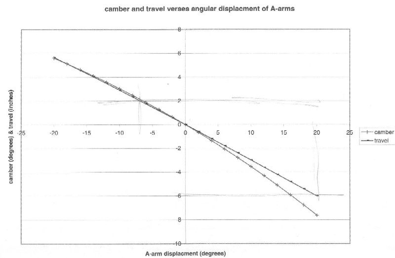
at 17.5” above the ground (at ride height). Having the top A-arm horizontal at ride height
is ideal for the camber response we want our suspension to have in roll:
negative camber in compression, positive in droop. The top A-arm has
the most effect on this because it is shorter.
the ground (at ride height). Having the top A-arm horizontal at ride height
is ideal for the camber response we want our suspension to have in roll:
negative camber in compression, positive in droop. The top A-arm has
the most effect on this because it is shorter.
For our upright to reach around the disc breaks on the rear, and
for good clearance while keeping the push-rod attachment point low, we wanted
the lower A-arm to slant down towards the wheel. To accommodate a 6”
disc break and put the drive axle roughly in the middle of the upright, we
settled on 9” vertical distance from pivot to pivot on the upright.
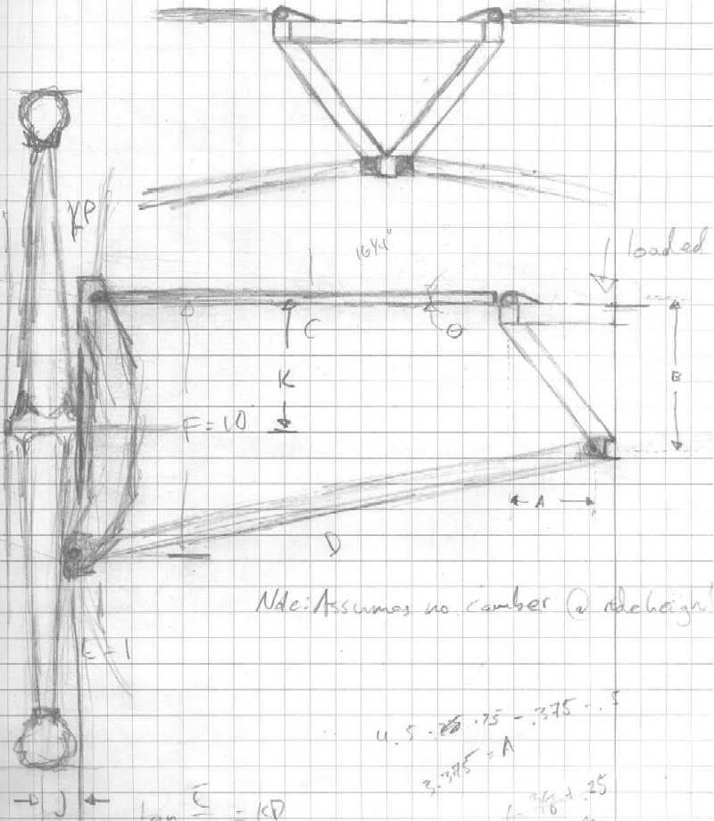
(
Sketch A-arm geometry
)
By looking at last year’s buggy we initially chose the distance
between the a-arm pivot points on the frame to be approximately 12”.
This would provide the proper geometry to take the horizontal forces from
the wheels during acceleration, braking, and obstacle encounters.
To keep jigging and manufacturing simple, we decided to leave the A-arms symmetrical
front to back. We saw no reason this would be a problem.
The upside-down triangle frame design produces increased negative caster on
the outside wheel of a turning buggy. This helps to reduce the undesirable
side loads. Last year’s buggy actually had a significant amount of
negative caster at ride height, presumably for this purpose. This made
sense, but such a design interfered with one of our planned improvements to
last year’s design.
One of our biggest complaints about last year’s buggy is the poor
steering response. This year, we hoped to solve the problem by designing
appropriate kingpin angle into our suspension to minimized bump-induced steering
and keep us from going off the course due to collisions with the simulated
lunar obstacles. Kingpin angle is the angle of the upright-A-arm attach
points from vertical when viewed from the front. Proper tuning of this
angle allows the turning axis to go through the point where the wheel meets
the ground. This eliminates bump induced steering and produces a light
steering response. We felt this was a key improvement that could be
made to our buggy design, and wanted to incorporate it. However, if
we designed for negative caster at ride height, this would require a very
large kingpin angle. Such a large kingpin angle would result in a very
short upper A-arm and therefore in excessively progressive camber.
It would also cause constant side loading of the wheels at ride height.
For all these reasons we decided to design for zero camber at ride height.
The lower upright-A-arm attach point was put as close as possible to the
spokes, resulting in a kingpin angle of about 8 degrees.
The use of kingpin introduces another steering problem. If
the upright-A-arm attach points are on a vertical line when viewed from the
side, then turning will cause both of the wheels to have positive caster.
This is actually desirable for the inside wheel, but very undesirable for
the outside wheel because it increases side loading. The solution to
this problem is to make the upper attach point further back than the lower
attach point. This is called caster angle. This also causes the
turning axis to hit the ground slightly in front of the point where the wheel
hits the ground. This will produce a slight self-centering tendency
in the steering, which is desirable. An appropriate caster angle is
one that is roughly the same as the kingpin angle. We calculated that
the upper A-arms should be attached 1.25” behind the lower ones.
A-arm tubing size calculations:
Calculating the tube sizes for the A-arms turned out to
be a much more difficult problem than we first anticipated. To choose the
sizes we first needed to know what stresses were involved. These were determined
by our loading criteria. We stated that the buggy must be able to
1.) Corner in excess of one gravitational constant
2.) Survive a two-foot fall
3.) Clear a six-inch curb traveling 20 mph
· Cornering
Last year these calculations were done by finding the centrifugal
force acting on the buggy in the turn (one or one and a half times the total
weight) and dividing that between the contact patches of the outside wheels.
With a total buggy weight of 100 lbs empty + 350 lbs riders, each wheel would
need to carry 340 lbs or so with a 1.5 safety factor. However, we were using
bicycle wheels that last year’s team had calculated to fail well below 200
lbs. We decided that a 200 lb side force at the contact patch of the wheel
was a reasonable upper limit including safety factor. Last year the team
calculated this turn while braking (add a force vector directed against the
motion equal to half the weight times the friction coefficient). We decided
that for this loading condition braking was negligible since the brakes were
rear mounted and would tend to break the rear end loose, putting it in kinetic
friction mode. From this 200 lb side loading condition it was easy to calculate
the forces on each A-arm using force couple and trigonometry. The tip of
each a-arm creates a force couple to counter the torque from the contact
patch. Each A-arm pushes about the axle with 195 lbs. of force. Dividing
this force into the two tubes using sum of the forces to zero yields:
Forces on front upper tubes each (tension) 210 lbs
Forces on front lower tubes (compression) 200 lbs
Rear upper tubes (tension) 212 lbs
Rear lower tubes (compression) 205 lbs
These were the forces just to keep the buggy in the curve. The
suspension pushrod added another vector to the a-arm node. For cornering
this force actually countered the contact patch induced torque thereby reducing
the forces on the A-arms.
· Two Foot Drop:
The next loading condition was a two-foot drop. Due to the suspension
we estimated a 400 lb average vertical force at each wheel with the maximum
at bottom out of 600 lbs. This would put the bottom A-arm in tension with
1600 lb force. Using the same methods as before yielded:
Forces on front upper tubes each (compression) 860 lbs
Forces on front lower tubes (tension) 835 lbs
Rear upper tubes (compression) 870 lbs
Rear lower tubes (tension) 840 lbs
This would be the effect of landing on ice, i.e. the wheels
do not give inward force. If landing on pavement or dirt there will be a
significant force inward by the wheels to counter increasing camber throughout
travel. This would oppose the compressive forces on the upper A-arms.
· 6” Curb:
The final loading condition was the 6” curb. This was by far
the most difficult to calculate. In the end we modeled the system using Working
Model 2D. The first time around we did not account very well for the give
in the tires (simply modeled it as solid rubber) and found the impact force
to be enormous. After changing the model a little bit the numbers were reasonable.
Instead of having a rubber wheel, we put in a spring to represent the tire.
We realized that although it may be feasible to make a buggy that could withstand
a 6” curb at 20mph, it was not possible to make a tire and wheel that could
withstand that impact. Assuming a square profile of the curb, we estimated
the k value of the tire to be around 240 lbs/in at 60psi (with the curb 1”
into the 2” wide tire roughly 4 sq in are displaced: 4 x 60 = 240) and 480
lbs/in at 120psi. We assumed mild damping of around 250 N-s/m. Assuming that
the tire should not compress more that 1.5” less the curb hit the rim and
buckle it, we modified the loading condition to 10 mph into the curb with
60psi tires. The results from the program are below:
· Hitting a 6” Curb at 10 MPH
Wheel:
Max x-direction: 650 lbs
Max y-direction: 400 lbs
Max loads on back tube of the lower-front a-arm: 900 lbs compression,
Max loads on front tube of the lower-front a-arm: 1300 lbs tension
Max loads on back tube of the upper-front a-arm: 900 lbs compression
Max load on the front tube of the upper-front a-arm: 900 lbs tension
These were the most severe loadings so we calculated tube
diameter from these values. We used Euler’s buckling formula for pinned-pinned
loading conditions to find the necessary tube diameter with 0.035” wall thickness.
Pcr = pi^2EI/L^2
For these loading conditions the closest diameter that met
the specifications was 5/8” diameter. For the front half of the A-arms 3/8”
tubing would have been ok. However two things prevented us from using this.
First there was the kick factor. We were afraid that running into an obstacle
or hitting the tube would buckle it regardless of the wheel loading. Second,
manufacturing would be made much more difficult by using unequal sized tubes.
The extra weight of using 5/8” instead of 3/8” on all the front tubes was:
(0.2205 lb/foot - 0.1271 lb/foot)11ft=1.0274lb
Saving one pound with the smaller tubing was not worth the
added manufacturing cost and risk factor.
· Some Thoughts:
Possibly the 6” curb loading condition should be rethought.
Hitting a curb at 20mph is a fairly severe impact (a car wheel would likely
buckle) and not very realistic for the racecourse. In addition, modeling
the situation is needlessly difficult. Another method to determine tube loading
is to attach strain gauges to the current a-arms with a voltmeter that records
a maximum value. Then ride the buggy into curbs around corners and everything
to get realistic numbers. Even though the calculated numbers say we are ok,
there is no better method than taking experimental data. The a-arms may still
be needlessly overbuilt.
Fabrication Notes:
In order to drastically improve the preciseness of the construction
of this year’s buggy, we set out with a goal to use an accurate jigging and
mitering process wherever possible on this year’s suspension. One main
jig was constructed in order to ensure that A-arms were fabricated to meet
correct length, angle, and position requirements where they were designed
to fit on the buggy. This process enabled us to construct 8 sets of
A-arms that fit the exact specifications of the design.
The first step in the construction process was to figure out
a way to accurately cut the tubes to fit to the inserts. The goal here was
to quickly reproduce a good enough miter to weld to. By ensuring the
A-arms were constructed as specified we were able to make certain that the
suspension would perform to it’s maximum potential. The main problem
we had to solve was keeping the two miters in the same plane.
Some of the first ideas were to tilt the mill in such a way
as to cut the hole to the specified angle. At first this fell through
because we could not figure out how to ensure the miters were in the same
plane. Another idea was find a way to drill an accurate hole and miter
the rest of the tube using a grinder or a sander. This idea however
is not very accurate and does not lend itself to reproducing 16 cuts.
In desperation, we consulted Glen Swan as to how he cut the angles in the
tubes he uses to make bike frames. The solution was surprisingly simple.
To keep the two miters in plane, two pairs of half-moon shaped blocks
were clamped to the tube prior to mitering, one on each end. This was
done on a flat table so that the blocks were in the same plane. We
then constructed a clamping apparatus that could be attached to a lathe where
the normal cutting or turning tool would attach. This clamped onto
one of the half moon blocks that were clamped to the tube. The tool
mount was then accurately set to the correct angle to ensure the hole was
cut at the proper angle. In normal lathe operation the piece spins
whereas the cutting tool stays stationary. We reversed this process
and placed a 5/8” hole cutter in the chuck of the lathe while keeping the
tube stationary. The process allowed us to cut all 16 A-arm tubes with
complete accuracy while using only one machine set up. Am similar setup
could have been used on the mill, but tilting the mill is slightly more tricky
than adjusting the angle on the lathe.
The 8 A-arms were constructed using 5/8” 4130 steel tube with
.035” wall thickness. Inserts were made to provide a place for the rod ends
to be screwed in. All inserts were made out of solid steel stock and
turned down to 0.555” outer diameter. The inserts were then cut to a
length of 1” and drilled and tapped to fit the accompanying rod-ends.
All of the frond rod ends were 3/8-24 and the back rod ends were 5/16-24.
The front rod ends were larger because our steering required high misalignment
rod ends. The front rod ends had to be mounted with the bolt vertically
to handle the steering angles, whereas the back could be mounted with the
bolt horizontally. Therefore the front rod ends had to reach large enough
misalignment angles to handle the whole suspension travel. The misalignment
requirements on the rear were minimal. We wanted no less than ¼”
bolts to go through the eye of the rod ends to handle to handle the breaking,
steering and suspension loads. For high misalignment rod ends, the
ball needs to be much larger for a given eye diameter. The high misalignment
series is therefore constructed larger and beefier in general. This
is why the thread on the front was larger diameter than that on the rear.
In the end it makes sense, since the front will encounter obstacles while
the buggy is still at speed, and will therefore experience higher loads.
The next step was to construct a jig that lined up the tubes
around the insert at the correct angle. We used a large flat piece
of aluminum with numerous attachment points in order to accommodate the various
lengths and widths of the A-arm. Once the lengths and widths of the
A-arms were determined we were then able to set  up holes on the jig plate that correctly held a mock aluminum frame in place
to constrain the movement of the tubes during welding. A block was
attached to one of the plate with a bolt placed threw it to hold the insert
in place. This held the two bushing inserts in the correct location
and the tubes were then fitted around these inserts. These inserts
were 5/8” OD tube that were later fitted with brass bushings in order to
allow the A-arm to travel smoothly over the bolt. Now the A-arm tubes
were completely constrained in all directions to the exact location of the
design specifications and were ready to weld. Tabs were the welded
to the frame at a distance equal to that of the insert fitted with the brass
bushings. By jigging up all the parts for the A-arms were able to ensure
that they were all constructed to meet the exact specifications required
in the design.
up holes on the jig plate that correctly held a mock aluminum frame in place
to constrain the movement of the tubes during welding. A block was
attached to one of the plate with a bolt placed threw it to hold the insert
in place. This held the two bushing inserts in the correct location
and the tubes were then fitted around these inserts. These inserts
were 5/8” OD tube that were later fitted with brass bushings in order to
allow the A-arm to travel smoothly over the bolt. Now the A-arm tubes
were completely constrained in all directions to the exact location of the
design specifications and were ready to weld. Tabs were the welded
to the frame at a distance equal to that of the insert fitted with the brass
bushings. By jigging up all the parts for the A-arms were able to ensure
that they were all constructed to meet the exact specifications required
in the design.
Performance / Lessons
Learned:
Overall the performance of the A-Arms lived up to all expectations.
The Caster and Kingpin angles ended up being correct and they were both a
huge success. This year we used thinner A-arms without any adverse effects
and they seemed to hold up just fine despite not being attached perfectly
at the nodes. The camber change through travel was also very good,
and the wheels held up just fine. A big change on this year’s buggy
is that the A-arms are interchangeable and could easily be replaced if broken.
This is much better than the previous design, which required side specific
arms that could only fit in one place. The addition of hex bolts at
all frame connections helped save time in assembly and added to the ease
of interchangeability of the A-Arms. We decided to use ¼” bolts
at upright-A arm attachment points because they were readily available, not
because of calculations. These bolts might be too small, but seem to
have held up fine through all riding to this point.
Rocker Assembly
Introduction
We discussed several options for solving the roller-clutch
assembly clearance issue described in the introduction
. The first option was to leave the suspension design exactly the same
and try to solve the problems by modifying other systems on the buggy.
We had already decided to use universal joints rather than constant velocity
joints on the outboard ends of the half shafts to save weight and reduce friction.
This would solve the high-angle friction problem we had last year.
The chain ring clearance problem however was still present,
and was actually exacerbated by our back-to-back rider configuration.
For the rear rider to pedal forwards but go backwards we had to incorporate
a gear reversal mechanism. For various reasons, we decided to wrap
the chain around some guides in front of the rear roller-clutch chain ring.
This made it all but impossible to build the rear drive-train around the
suspension. We also made the decision to mount the steering linkages
inside the frame rather than below it. This made the space tighter
in the front half of the buggy as well. We decided that the suspension
would have to be put somewhere else.
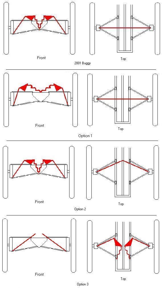
There were three major options we considered for relocating
the suspension.
1. Keep the suspension in the correct plane, but widen the attach points of
the rockers until the shocks are nearly horizontal.
2. Rotate the plane of the rockers towards the middle of the buggy around
vertical axes through the wheel centers.
3. Mount the suspension in planes defined roughly by the top outside frame
members and the point of the lower A-arms.
Options considered for rocker-pushrod arangement
The first option solved the clearance issue, but had two major
problems. The first was mounting the rockers to the frame.
Making the shocks nearly horizontal meant that the mounting points needed
to be at least 18” apart. This could have been achieved by building
extensions on the frame, but they would have had to be very strong to take
the high loads from the wheels. This could have been done, but would
have involved extra work and extra weight. The second problem was more
serious. We had decided that the one-inch tubing used for the lower
A-arms last year was excessive for any loading conditions with the exception
of the bending moment caused by the push rods. We wanted to decrease
this tube to 5/8” to reduce weight. This required attaching the push
rod as close to the node as possible. To do this, the push rod could
not come straight down to the attachment point, as it did in last year’s suspension,
and in option 1. This would have caused interference with the half
shaft, particularly on the front where the steering causes the half shaft
to move from side to side on the outboard end. The solution we decided
on was to have the push rod to come down from the back to clear the half
shaft, attach to the node of the A-arm, and be properly positioned to encounter
bumps hitting the front of the wheel.
Option 2 solved the problem mentioned above, and made clearance
for the roller clutch assembly. Several problems with this design however
forced us to abandon it as well. Keeping the rockers vertical and moving
them towards the seat created potential interference with the rider’s legs.
We had planned to keep the rider’s rear as close to the top of the frame
as possible to keep the center of mass low for cornering. We feared
that Option 2 would prevent us from doing that, or else cause discomfort
or even prevent the rider from pedaling. In addition, the placement
of the shocks interfered with our intention to move the steering inside the
frame. This design was also susceptible to the problem of side loading
the rockers we discussed earlier.
Option 3 was the ideal choice as far as interference was concerned.
With the shocks mounted horizontally and lengthwise on the top of the frame
we could eliminate all interference issues with the drivetrain, the rider
and the steering. This solution also eliminated interference with
the half shafts and properly supported loads due to hitting bumps with the
front of the wheels. For these reasons we decided to try to solve all
the problems associated with option three and implement it if possible.
There were four major problems we had to solve:
1. The geometry was out of plane, and could potentially have
lead to severe side loading of the rockers.
2. Mounting the rockers on top of the top frame bars would put the frame
members in severe bending and torsion. The frame would not withstand
these forces without a lot of reinforcement.
3. The rockers and shocks would have to be kept far enough apart not to hit
each other, and to leave enough clearance for the chain to pass from the
hub shifter to the roller clutch assembly. This meant some support
structure would have to be built outboard of the frame.
4. This design put the push-rods at a smaller angle with the horizontal than
the other designs. This meant that the push-rods, rockers and shocks
would have to withstand a larger total load to support the same vertical
load at the wheel.
The first problem was solved by allowing the rockers complete
rotational freedom around their attachment points. They were mounted
with a high-misalignment spherical bearing capable of traveling 23 degrees
in each direction. The rocker was then mounted to both the shock and
the push rod using cylindrical pivots, to keep those three elements always
in plane. The plane is defined by the rocker-frame attachment point,
the shock-frame attachment point, and the varying attachment point between
the push rod and the A-arm, each mounted with a spherical bearing or rod end.
This set up allowed the rocker to adjust to varying push rod angles, and
thereby eliminate any side loading of the rocker.
The second problem had to be solved in a way that was strong
enough but not too heavy. The solution to problem 2 would also have
to solve problem 3. We decided the best method was to put a horizontal
beam under the top rails of the frame to support the rockers. This
could be extended out beyond the width of the frame to solve problem 3.
This also helped to lessen the difficulties we faced with problem 4 by increasing
the angle with the horizontal. The horizontal beam would be slightly
thicker and wider than the stock we used on the rest of the buggy.
We calculated that 1” x 0.058’ wall would be strong enough to support the
largest loads we expected out of the suspension. The tabs that would
support the rockers were made out of 0.063” sheet, and reinforced to prevent
buckling. Though this was some of the heavier duty construction on
the frame, it would contribute significantly to it’s weight, but we decided
this was appropriate given the that the entire weight of the buggy is supported
through the suspension. This design did not account for any lateral
loads this cross member might have needed to support, but we intended to
attach the trussing directly to the outermost part of the cross member, so
it would help support any side loading and transfer the weight of the buggy
to the suspension. The crossbar had an additional benefit of providing
a potential mounting point for the roller clutch assembly, which would have
to be arranged for somehow anyway.
Problem 4 simply required evaluating the weight impact that
would result from making the suspension strong enough to support the loads
involved. Calculations revealed that 5/8” x 0.035” tubing at 16” long
would be strong enough to take 1000 pounds in buckling (with a safety factor
of 2). This was the maximum predicted loading of our suspension, given
critical damping and impacting a curb 6” high at 10 mph. The length
of the push rods in our final design turned out to be somewhat less, roughly
12”, so we were confident that this would be sufficient. The rockers
would be made out of much thicker material than would have been necessary
to withstand buckling, the reason being to prevent pullout of the pins at
the attach points. We were therefore not concerned with their ability
to handle the compressive loads. (Rocker design will be addressed more
completely in the rocker section) Making the shocks strong enough simply
involved choosing an appropriate spring rate. (More on this in the
shocks section) Therefore, the only impact on weight due to the increased
load on the suspension was in the push rods and the crossbar on the frame.
This amounted to less than a pound on the whole buggy, so we were willing
to take the additional weight for the clearance benefits. In the end
we settled on option 3.
Shocks
Design Notes:
Last year we used Fox’s coil spring shock line, the “Vanillas.”
The reliability, durability, adjustability, and low cost of these shocks made
them a perfect choice for the old buggy. Fox shocks are not the most inexpensive
shocks available, however their many features make them ideal for our use.
Fox shocks are available at any bike shop and have many different strength
springs available. They also have externally adjustable compression and rebound
dampening knobs, allowing them to be tuned for the buggies suspension easily
and on the fly.
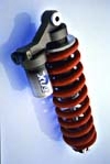
Vanilla Shocks
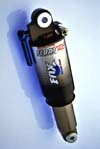
Float Shocks
We considered using Fox’s air shock line, called the “Floats”
this year. The advantage to these is that they offer adjustable spring
rate, which would allow us to quickly adjust for different riders.
This is not a necessary feature for the competition, since all of the riders
we are considering are roughly the same weight. It would allow us some
flexibility in calculating the required spring rate (which is no easy task,
given the complexity of the suspension, and our uncertainty about the buggy
weight, the exact distribution of rider weight and the exact magnitude of
the forces we are likely to encounter). If we bought springs and found
they were the wrong spring rate, it would cost us $50 to replace them.
The floats do not offer quite as much travel as the vanillas, but this would
not be a problem since we could adjust the rocker geometry as necessary to
compensate. The main disadvantage to the floats is that they require
more maintenance and are less reliable. They must be checked before
each ride, since the air can leak out around the seals. They are also
less durable and therefore more prone to failure. In the end, partially
for reliability, and partially due to the success of last year’s suspension,
we went with the vanillas.
Because of our high travel requirements, we used the highest
travel Vanilla’s available. These are 8.75” long with 2.75” of travel.
Springs are available with spring rates from 300 lb/in to 1200 lb/in in 50
lb. increments. There was some confusion in calculating the necessary
spring rate, because loading calculations for the front included the damping
loads the springs would have to handle. Due to a miscommunication, these
same loading values were used to determine the necessary spring rates, and
the shocks we purchased were too stiff. Since accurate calculations
were never done on the rear, we had to guess what spring rate was necessary
there. In the end, after some mixing and matching with last year’s buggy
(which was too soft on the front anyhow) we achieved spring rates that felt
right on the buggy. We used 450 lb/in springs on the front and 300
lb/in on the rear. The smaller spring rate on the rear was due partially
to the fact that the rear rider is much lighter than the front, but was also
due partially to the narrower wheels on the rear which resulted in a steeper
push rod angle, causing the push rod to take less load for the same wheel
loading.
Rockers
The rockers on the 2001 buggy were CNC’d out of aluminum. This year’s
team lacked the necessary experience to do this. We were forced to
seek alternative designs. For the same reasons we chose it for other
parts of the buggy, we leaned towards chro-moly for its manufacturability,
low cost, strength and weldability. The idea was to use two parallel
plates with holes drilled in them for pins. Theoretically this could
have sufficed for the entire design, however, the fact that the rocker and
pins would have to keep the entire linkage system in plane made two floating
plates undesirable because they could rotate relative to each other, allowing
the pins to twist out of the correct plane. A box section on the compression
side was desirable because it would prevent the two plates from buckling.
This however would not be completely sufficient to keep the two plates from
twisting relative to each other. Another factor came into play as we
tried to solve this problem.
Since we had decided to go with option 3, the rocker-frame
attachment point had to house a spherical bearing. The question was
whether to mount this bearing to the rocker or the frame. The spherical
bearing would have to be pressed into a precisely machined tube attached
to either the frame or rocker. One of our goals was  to make our rockers quick and easy to produce, so putting the bearing in
the rocker could have made this difficult. On the other hand, putting
the whole frame in the arbor press could have been a daunting task.
Also, if the tube were mounted in the rocker, it could provide it with additional
torsional strength. That, in conjunction with the stiffening member
on the compression side, would keep the plates from twisting relative to
each other. With some further thought we realized that we could turn
a substantial length of tube down all at once, and cut it into many spare
bearing-tubes for making extra rockers. Therefore, we decided
to mount the bearings in the rockers. It is worthwhile to note that
we came up with no strong arguments either way on this point, and it could
easily have been done either way.
to make our rockers quick and easy to produce, so putting the bearing in
the rocker could have made this difficult. On the other hand, putting
the whole frame in the arbor press could have been a daunting task.
Also, if the tube were mounted in the rocker, it could provide it with additional
torsional strength. That, in conjunction with the stiffening member
on the compression side, would keep the plates from twisting relative to
each other. With some further thought we realized that we could turn
a substantial length of tube down all at once, and cut it into many spare
bearing-tubes for making extra rockers. Therefore, we decided
to mount the bearings in the rockers. It is worthwhile to note that
we came up with no strong arguments either way on this point, and it could
easily have been done either way.
The other two spherical attachment points could easily be handled in the
same way as they were last year. The shock can have a spherical bearing
ground down and pressed in using the procedure described in last year’s design
report. (2001 Cornell
Moonbuggy
) The spherical pivot on the outboard end of the push rod could use
a standard spherical rod end as was used last year. The cylindrical
pivots on the rocker were also straightforward. The shocks are designed
to be used with an in-plane bicycle setup, and are easily attached to the rocker using appropriate
brass bushings. The push-rod rocker connection was achieved with a
non-spherical rod end and appropriate bushings. These rod-ends were
only available in coarse, right-hand thread. We planned to use a turnbuckle
style push rod to adjust the ride height as was used last year. The
coarse thread actually worked well for this purpose because it allowed more
adjustability with fewer rotations of the push rod. Because the inboard
rod-ends had to be right-hand thread, the spherical rod-end on the outboard
end had to be left-hand thread.
in-plane bicycle setup, and are easily attached to the rocker using appropriate
brass bushings. The push-rod rocker connection was achieved with a
non-spherical rod end and appropriate bushings. These rod-ends were
only available in coarse, right-hand thread. We planned to use a turnbuckle
style push rod to adjust the ride height as was used last year. The
coarse thread actually worked well for this purpose because it allowed more
adjustability with fewer rotations of the push rod. Because the inboard
rod-ends had to be right-hand thread, the spherical rod-end on the outboard
end had to be left-hand thread.
The final design decision to be made about the rockers was
how far apart the two plates should be. Since the rocker was going
to pivot between two parallel plates attached to the frame that would support
the pin through the spherical bearing, it would need to be as narrow as possible.
The width was ultimately decided by how wide the shock was at the attach point
after the bushings were installed. The rocker plates were 5/8” apart,
¾” wide on the outside.
Design Notes:
Rocker Geometry:
When designing the rocker geometry, we had two main
concerns:
1. The motion ratio (wheel travel/shock travel) had to be
appropriate to get the 8” of wheel travel we wanted from the 2.75” of travel
in our shock.
2. We wanted a rising rate to allow the suspension to handle small bumps
well, without bottoming out under heavy loads.
Once these goals were accomplished, we could tune ride height
and maximum loading by adjusting spring rate and preload on the shocks.
Damping and rebound are also adjustable on the shocks.
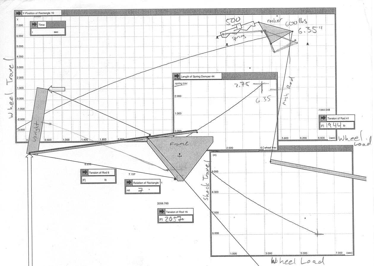
We decided that since our push-rod-rocker-shock assembly
was in plane, a two-dimensional computer-modeling program would be ideal
to tune our rocker geometry. The problem turned out to be more complicated
than this. The out-of-plane design of our suspension caused the rocker
moves in a complicated plane that changes throughout the suspension travel.
The A-arms on the other hand, moved in a vertical plane. It turns out
that the motion ratio and progressiveness of the suspension is affected by
the geometry in both planes. The motion of the push-rod and A-arms in
the vertical plane  creates a large rising rate which is built into the design. This rate
was so large that we had to counteract it by designing a large falling rate
into our rockers. The problem was so complicated that it was hopeless
to solve it without the aid of computer modeling. However, the only
software that was available to us was working model
creates a large rising rate which is built into the design. This rate
was so large that we had to counteract it by designing a large falling rate
into our rockers. The problem was so complicated that it was hopeless
to solve it without the aid of computer modeling. However, the only
software that was available to us was working model 2-d. This software allows rods, ropes pulleys, springs and dampers
to be modeled in a two-dimensional environment. (Apparently a 3-d version
of this software exists, but we had neither the resources or the expertise
to use it) In the end, we made a complicated model that connected the
motions in the two different planes. With a number of approximations,
we felt we had created a model that approximated the motion of the buggy
reasonably well. Using this model, we tuned the rocker geometry to
give us the performance we wanted.
2-d. This software allows rods, ropes pulleys, springs and dampers
to be modeled in a two-dimensional environment. (Apparently a 3-d version
of this software exists, but we had neither the resources or the expertise
to use it) In the end, we made a complicated model that connected the
motions in the two different planes. With a number of approximations,
we felt we had created a model that approximated the motion of the buggy
reasonably well. Using this model, we tuned the rocker geometry to
give us the performance we wanted.
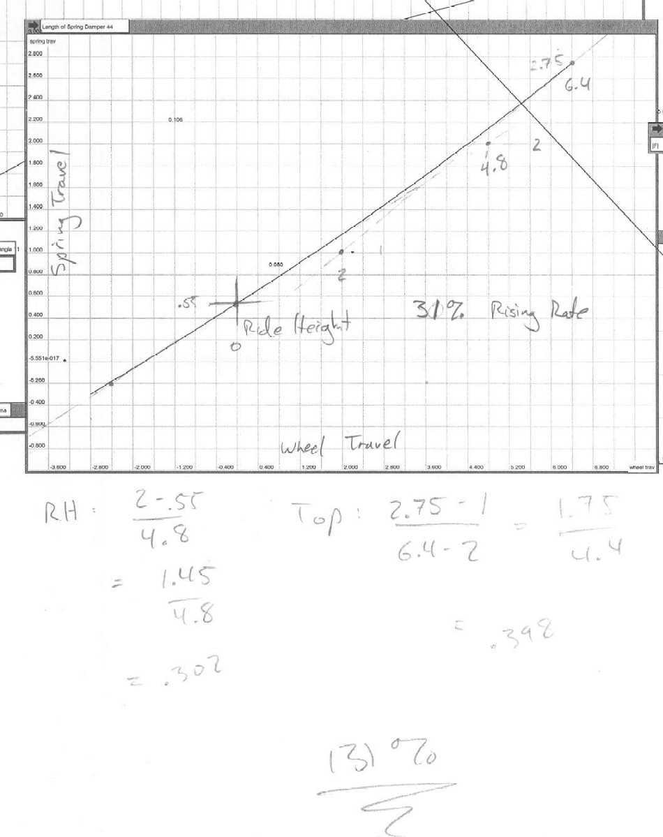
The motion ratio was controlled by changing the ratio of
the radii of the shock attach point and the push rod attach point as measured
from the frame attach point (Rs and Rp in the figure). Greater Rp /
Rs results in greater motion ratio. The progressiveness was controlled
by changing the angles theta-s and theta-p shown in the figure (these angles
are defined when the suspension is at top out). The progressiveness
relies on the nonlinearity introduced by the arcs that the attach points travel through.
This nonlinearity results from the change in mechanical advantage as the
angles theta-1 and theta-2 change throughout the suspension travel.
Therefore, tuning the rate also involves choosing an appropriate size for
the rocker (that is, two inches of shock travel must introduce an appropriate
amount of nonlinearity to produce the desired progressiveness
nonlinearity introduced by the arcs that the attach points travel through.
This nonlinearity results from the change in mechanical advantage as the
angles theta-1 and theta-2 change throughout the suspension travel.
Therefore, tuning the rate also involves choosing an appropriate size for
the rocker (that is, two inches of shock travel must introduce an appropriate
amount of nonlinearity to produce the desired progressiveness
Using an iterative method, we eventually settled on a front
rocker design that satisfied our design criteria. Unfortunately, a
corrupted floppy disk and lack of time to start the program over again prevented
us from doing the same for the rear rockers.
The geometry on the rear was significantly different from
the front, mostly because of the narrower wheel placement. We used
the same rockers from the front on the rear, hoping they would work, but
found that they were too progressive and too stiff (the latter problem could
not be solved by changing springs because we were already using the softest
ones available). We fixed these problems by modifying the attach points
on the rear rockers until we were satisfied with their performance, and then
constructing new ones. In this situation, we were glad for the simple
and low cost design of our rockers.
The working model 2-d software not only helped us fine tune
our rocker geometry, but calculated the loads that could be expected in the
push-rod and on the frame, helping us decide what size stock would be necessary
at those locations.
Pins and Bearings:
The most critical pin and bearing decision on the
rockers was the frame-attach-point. This point would need to support
the resultant force due to both the shock and push rod. With the shock
fully compressed using 450-pound springs it would put roughly 1000 pounds
of force on the rocker. A slightly smaller force from the push rod
would be oriented at roughly 90 degrees to the force from the shock (slightly
smaller because the push-rod/shock motion ration was slightly greater than
one). A rough estimate of the resultant is 1500 pounds, inwards and
towards the back of the buggy. The spherical bearing would have to
house a pin strong enough to support this load. The bearing would have
to have high misalignment tolerance because the suspension was designed to
move the push-rod through more than 30 degrees. This meant the OD of
the bearing would have to be much larger than the pin, and too large of a
pin would make the bearings very heavy. In addition, enough space would
have to be left on top and bottom of the bearing to allow the rocker its full
range of motion. Care would have to be taken to avoid putting excessive
bending moments on the pin.
Calculations showed that a 3/8” pin would support the
loads with a safety factor close to 2. This corresponded to a high-misalignment
spherical  bearing with an OD of 0.906” and an eye length of 13/16”. This bearing
was actually pretty difficult to track down, because National Rod Ends as
out of stock. We ended up getting them from Kaman, but they were not
cheap. At almost $40 apiece, they were by far the most expensive part
of the suspension aside from the shocks. The weight of these bearings
was a factor as well. At 0.068 lbs. each, the four of them contributed
a total of 0.272 lbs. to the buggy.
bearing with an OD of 0.906” and an eye length of 13/16”. This bearing
was actually pretty difficult to track down, because National Rod Ends as
out of stock. We ended up getting them from Kaman, but they were not
cheap. At almost $40 apiece, they were by far the most expensive part
of the suspension aside from the shocks. The weight of these bearings
was a factor as well. At 0.068 lbs. each, the four of them contributed
a total of 0.272 lbs. to the buggy.
To get the necessary angular rocker travel, it was calculated
that the gap in which the rocker was mounted would have to be on the order
of 1.125” wide to accommodate a ¾” wide rocker. Spacers would
have to be placed between the bearing and the plates to reduce bending loads
on the pins, but these spacers could not interfere with the motion of the
rocker. We manufactured the spacers ourselves out of aluminum with a
taper on them, so they would have sufficient breadth to support the pin, but
also stay clear of the motion of the rocker.
The other two pin sizes were decided based mostly on the
standard available bushings and rod ends. The bolt holding the shock-frame
attach point would have to be ¼” because that was the only size spherical
bearing that would fit in the shock. This is what was used last year,
and it held up fine (although last year they used slightly softer springs)
Based on available bushings and rod ends, the pins for the shock-rocker and
push-rod-rocker attach points were 3/8” and 5/16” respectively. This
would be more than strong enough.
Mounting:
Mounting shocks and rockers to the frame required
care as far as bringing the loads to nodes. Since these mounts would
take some of the largest loads on the buggy, the mounts would have to be
beefy and therefore heavy. The suspension mounting points were also
likely to define the nodes and trussing on the buggy. It was therefore
in our interest to incorporate the suspension mounts with other elements
on the buggy. It has already been mentioned that the suspension cross-bar
also serves to support the roller-clutch assembly. This is a dramatic
improvement over the heavy aluminum support system that was used last year.
We hoped to use this technique for the shock mounting points as well.
Because we wanted the push rods to be properly positioned
to encounter loads from the front of the buggy, the suspension was one of
the few things  that would not be symmetric on the two buggy halves. The shocks would
always point forward from the rockers. On the front, it was convenient
to incorporate the suspension mounts with the shifter hub/crank support mounts.
Because of the high loads the mounts would encounter, we decided to build
a 0.063” box structure covering the entire front corners of the buggy.
If we had not done this, the shock mounts would have been welded to the sides
of the frame top tubes, with a minimum of a 1” lever arm. This could
easily have resulted in bending loads that could compromise the frame.
We anticipated potential loads as high as 1000lbs at the shock attach points.
that would not be symmetric on the two buggy halves. The shocks would
always point forward from the rockers. On the front, it was convenient
to incorporate the suspension mounts with the shifter hub/crank support mounts.
Because of the high loads the mounts would encounter, we decided to build
a 0.063” box structure covering the entire front corners of the buggy.
If we had not done this, the shock mounts would have been welded to the sides
of the frame top tubes, with a minimum of a 1” lever arm. This could
easily have resulted in bending loads that could compromise the frame.
We anticipated potential loads as high as 1000lbs at the shock attach points.
On the rear of the buggy, the shocks did not mount near
the crank support mounts, the mounted midway down the frame top tubes.
Because of the bending loads described above, we were hesitant to mount the
shocks without putting a crossbar across the frame at that point. At
first this seemed like a lot of unnecessary material, until we realized that
the crossbar would double as a mount for our seat rail. 0.063” reinforcing
gussets were welded between the frame top tubes and the seat crossbar to
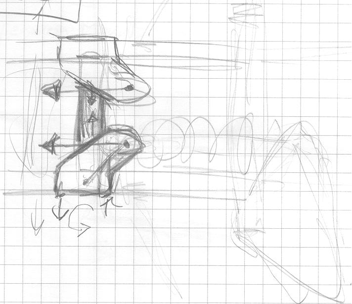
support the load of the shocks. (
Early shock mount sketch
)
In the end, all of our suspension/frame attach points
were incorporated with other buggy systems, making trussing simpler and reducing
the weight of the frame.
The outboard attachment points were done last, when
the buggy was nearly assembled so we could visualize the location of the
half shafts as the buggy moved through suspension and steering travel. (this
was, unfortunately, quite beyond the range of our solid modeling capabilities)
On the back, it was easy to bring the mount almost to the tip of the A-arm.
We were actually hindered the most by the intrusion of the upright over the
top of the bottom A-arm. This is one area where a complete design beforehand
could have been beneficial. On the front, the steering motion of the
Half shaft forced us to mount the push rod slightly more to the rear, but
still close enough to the node that we were not concerned about the bending
moment on the lower A-arm tube. In order to alleviate all worries about
this bending load, we put 0.040” plates spanning the tips of the lower A-arms.
The idea was to transfer some of the load to the other A-arm tube.
This also simplified the mounting of the push rod tabs, particularly on the
rear where they could be closer to the centerline of the A-arm. These
tabs were made out of 0.063” sheet in order to withstand pullout and buckling
loads.
Fabrication Notes:
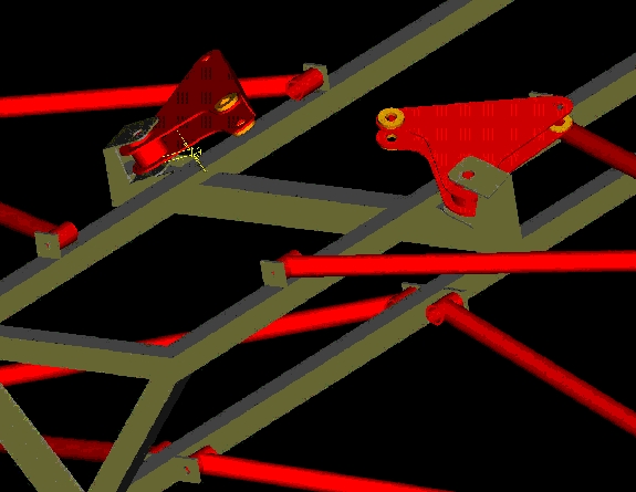
Rockers:
This year the fabrication of the rockers was
much simpler than the method used last year. With a lack of CNC programming
experience present on this year’s team we decided we would be better off
finding an alternative way manufacture the rockers. Making a change
much like the one made on the uprights we decided to move away from solid
one-piece aluminum to a box style rocker made using steel plate .063” thick.
The three critical holes were drilled in the plate using a mill. The
final rocker design was drawn on paper and this paper was then attached to
the plate. The steel was then cut and ground until the piece matched
the size of the paper design. This process may not be the most accurate
but the overall dimensions of the rocker are not critically important.
The most important part of the rocker design is the location of the 3 holes
that attach to the pushrod, shock and frame. As long as these holes
are all in the correct place in relation to each other then it is ok if the
rest of the steel is off by a few thousandths.
Once the plates were cut the bearing tubes were made
out of 1” OD chro-moly. This was the most difficult part of fabrication
because in order for the bearings to be press fit into these holes, the tube
had to be bored out to a tolerance of 0.9055" (+0, -0.0005).
Once the tubes were bored out and cut to length, the rocker was welded together.
The spherical bearings were then pressed into the tube. The rockers
were attached to the shock and pushrod using a series of pins, spacers, E-clips
and bushings. The E-clips were used instead of bolts because there
was concern that bolts would be loosened by the constant rotation of the
pin. The thread of a bolt also weakens it significantly. Pins
with E-clips eliminated these problems.
Inserts:
We used rod ends in several of the joints
in our suspension. They were at the outboard ends of our A-arms, and
at both ends of our push-rods. Inserts were made to fit the ID of the
tubing, drilled and tapped for the appropriate rod ends. The tubes
were cut at an angle to provide a longer weld attaching the insert to the
tube. Inserts is an area in which some improvements could be made.
The inserts were made 1” long because we wanted to leave as little of the
rod end exposed as possible, yet leave some room for adjustability.
Having too much of the threaded part of the rod-end exposed makes it a likely
failure point. The threads reduce the strength of the rod, having it
extend very far from the insert can lead to bending loads. We were
most worried about this in the case of impulse bump loads on the A-arm rod-ends.
We therefore designed for leaving two threads exposed. If it became
absolutely necessary to move the rod end in further than two threads from
the calculated location, we planned to cut down the insert. For this
reason, the inserts were all made 1” long.
An inch is absolutely unnecessary to carry the loads
involved. In most cases 4 or 5 threads would suffice. It seems
like the weight involved would be minimal, but there are 28 such inserts
on the buggy, and it could be significant.
Another note is that the rod ends on the outboard
end of the push-rod are ¼-28 thread. This is arguably insufficient
for the thousand pound loads the push rods can experience, especially if
a lot of the rod end is exposed to accommodate a heavier rider. These
rod ends were supposed to be 5/16-24 by design, but an ordering mistake left
us with a size smaller. This is a possible point of failure and should
be changed on next year’s buggy.
Performance
/ Lessons Learned:
Overall the final design of the rockers performed
exceptionally well. They allowed for the inboard mounting of the suspension
and smooth, progressive suspension travel. The final design was also strong
enough and do not show any signs of wear or cracking.
We learned our most important lesson this year the
first time we took the buggy out for a test run. We had debated whether
it was necessary to put a stiffening plate between the two parallel plates
on the side of the rocker that was in compression, to prevent it from buckling.
Since we had not performed any calculations, we did not know whether this
would be necessary. We thought it was a good idea, but it was not high
on our list of priorities. The stiffening plate had not been welded
on when we took the buggy out for its first test run and one of the rockers
buckled. We hastily welded on the plates, making the rocker much more
rigid and allowing it to handle the loading. The rockers simple construction
allowed us to make a replacement for the buckled rocker in no time.
Once the plates were welded on the rockers did not fail again. Such
a failure during the race would have been costly, emphasizing the importance
of finishing the buggy in time to test it before competition.
Our new rocker design performed up to all expectations.
The new rockers were made at a comparable weight to the ones on he old buggy
but they do provide some distinct advantages. The new design is much
easier to manufacture, much easier to tweak, and also much cheaper.
There are some areas though that the rockers could still be improved.
Using the same style as on the old buggy it would have been impossible to
save any more weight of the rockers because they could have failed if they
were any thinner. However, on the new design weight can definitely be
saved. A new design could use less material in order to decrease weight
while still making rockers that are strong enough to handle the loading.
The thickness of the plates was determined by the pin-pullout loads.
This means that material could be removed from the rest of the rocker in
order to save weight without losing performance. Our rockers were of
comparable weight to last years, but we feel our design would allow them
to be much lighter.
 the ground (at ride height). Having the top A-arm horizontal at ride height
is ideal for the camber response we want our suspension to have in roll:
negative camber in compression, positive in droop. The top A-arm has
the most effect on this because it is shorter.
the ground (at ride height). Having the top A-arm horizontal at ride height
is ideal for the camber response we want our suspension to have in roll:
negative camber in compression, positive in droop. The top A-arm has
the most effect on this because it is shorter. 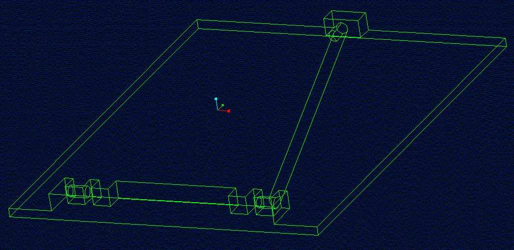
