
Overview: Welcome to Our Buggy
The purpose of this page is to give you a general idea of what the '02 Moonbuggy looks like and how it works. If you'd like a more detailed description of a particular part, check out the full design report or feel free to contact us and ask away!
We began with a frame that is based on triangular trussed structures. 4130 chrome-moly steel is used for the frame tubing because its advantages over other materials such as aluminum and titanium, which pose many difficulties in the fabrication process. 4130 chromoly is easy to weld and widely available, making it the metal of choice for Cornell Moonbuggy this year as well as last.
A triangular cross section, wide at the top and narrow at the bottom, makes for increasing camber in the wheels through the suspension travel, which is desired to ensure wheel strength. The wide top is also helpful to place components on the frame, including the suspension, steering, and drive train components.
Stresses in the frame were analyzed after applying dynamic loading conditions and varying the frame and tubing parameters. The tubes were chosen such to provide a factor of safety of 2 for the frame under the conditions of a two-foot fall and being ridden into a bump roughly the size of a curb at 20 mph.
A large aluminum jig was used to ensure a strong and well-aligned frame. The jig was made to provide precise positioning for the frame during the welding process and susequent cooling. The jig made mitering the tubes much easier and insured that all tubes were at right angles to each other. TIG welding was used to join the tubes because it makes for strong, light, and clean joints.
We chose a four-wheel independent A-arm suspension design to allow each wheel to react individually to obstacles. This makes the buggy versatile and able to handle varied terrain. An A-arm suspension was chosen because it has proven performance and fits the design of our frame well. Several other types of suspensions were initially examined, but none were as easy to implement with results as predictable as the A-arms. The forces are easily brought into nodes, which could be well supported with a trussed frame.
|
|
|
| A-arm with pushrod/rocker design |
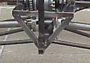
Basic inverted triangle frame desig |
The suspension is composed of upper and lower a-arms connected to the frame, an upright at the wheel, and is supported by a pushrod-rocker design. The inverted triangular frame design and different length upper and lower a-arms creates a parallel linkage, which causes the wheel camber to increase as the buggy goes through its travel. This makes the buggy more stable in turns and results in less side loading on the wheels.
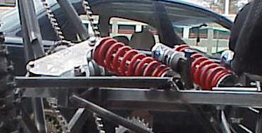
The pushrod, rocker and shock suspension design that supports the buggy has many performance benefits. Our rocker design achieves the appropriate motion ratio so that the full travel of the shocks provides desired wheel travel (8” in our design). In addition the rocker design provides for a rising rate to allow for a softer ride for small bump and prevent bottoming out under extreme circumstances.
By attaching the pushrod as close as possible to the upright on the a-arm we minimize the bending moment on the a-arm. The reduced bending moment allows for a lighter a-arm design. A horizontal rocker position permitted the pushrod to get as close to the upright without interfering with the halfshaft. Our pushrods slant from the wheel towards the back of the buggy orienting them to help reduce frontal loads on the bottom a-arm.
By mounting our rockers in a non-vertical plane we eliminated any confliction with drive train elements and allowed for the slanted pushrod arrangement. The large travel of our suspension results in a large angular variation of the push rod, and would therefore impart significant side loading on a traditionally mounted rocker, that is, one with only one rotational degree of freedom. We solved this problem by mounting our rockers with spherical bearings, and constructing the pushrod-rocker-shock arrangement to stay coplanar.
|
|
|
| Sideways mounted shocks on this year's design |
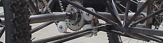
Full View of Reversed Drivetrain |
The design of the drive train for the Cornell Moonbuggy results in several key performance benefits. The use of internal hub shifters eliminates the need for a cassette of gears and derailleurs. The chain lines and chain tension are therefore fixed throughout the drive train, allowing the use of stronger and wider single-speed chain in the place of common narrow shifting chain. This considerably decreases the chance of chain derailment during riding as well as during assembly.
To allow our four-wheeled vehicle to round corners, a differential must be inserted in each axle to permit the outside wheel to spin faster through the corner. We designed a roller-clutch assembly for this purpose so it could be smaller and lighter than commercially available units. The system also provides power to the slowest wheel so that the buggy remains powered even if one wheel loses traction.
The axles were designed from a large diameter hollow tube. Tube axles can be made lighter than solid axles and still transmit the same torque. Furthermore, the larger diameter results in smaller loads at the torque transfer points. Keyways were used to transfer torques between different components of the drive train.
The axles at the wheel are made larger than a typical solid axle to ensure that the wheels remain rigidly supported and are very strong while minimizing weight. A large, hollow axle is much stiffer and can handle larger torques and bending forces for the weight. To minimize stress concentrations in the axle, the hub was attached away from the points of bending and shear stresses, where the only force applied is torque. Strength in this area is important because it is a cyclic loading area where fatigue strength needs to be considered. Chrome-moly steel was used here because it has strong infinite fatigue strength.
Disk brake mountain bike hubs with downhill rims are used to make strong, reliable wheels. The torque is transmitted to the wheels through the disk brake mounting holes in the hub. The brakes were also mounted directly to the wheels through the disk brake holes. By braking the buggy at the wheel, as opposed to braking at the axle, the torque of breaking is never transferred through the axle, which prevents extreme loading of the core drive train.

Back-2-Back Baby!
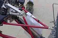
Probably the most striking feature of our design is the rearward facing direction of our rear rider. We chose this configuration for many reasons. Due to the in-line seating position required by our four-wheel-drive system in which each rider powers his or her axle independently, it was difficult to fit a forward facing tall rider on the rear without increasing the wheelbase or cantilevering the rider behind the rear axle. We disliked both of these options due to the adverse handling consequences. By turning the rear rider around we were able to fit any sized rider we wanted by extending their legs out from the buggy. This also allowed a smaller overall frame and a shorter wheelbase to allow tighter cornering. By putting the two riders back to back the weight become more centered in the buggy giving better handling. Also, the drivetrain and chainline were greatly compacted reducing the possibility of chain derailment, a common problem on the ‘01 buggy. From a manufacturing standpoint, turning the rear rider backwards made building the buggy more efficient since the two halves were nearly symmetric. Parts could be made twice for both halves rather than uniquely manufactured for each side.
The primary concern with the design was that the rear rider would not be able to perform as well as in the forward position, but after some test runs with a backwards seat mounted on the ’01 buggy we were convinced that the same or better performance could be achieved by the rear rider after a small adjustment period.
After we built the design we realized some additional benefits as well.
For instance when climbing hills, the rear rider is nearly standing vertical
and is in prime position to power the buggy up the hill. Also the rear rider
has a completely unobstructed view giving the two riders 360 degree view
coverage at all times. This could potentially be very beneficial for exploratory
missions such as those of the original moonbuggies.