
A standard pedal method of capturing rider power is used because it’s a well developed method that most people are accustomed to and efficient at using. In addition bicycle parts are readily available for purchase and are relatively inexpensive. A combination of mountain bike and BMX parts were used where they’re benefits were determined to be best.
To allow the buggy to fold in its basic design, the crank assemblies would have to fold in. To fold the cranks without changing the chain length the cranks would have to fold about an axle that the chain would rotate about. By fixing the chain length the chain could always remain in the same tensioned state while folded or extended. Because it wasn’t ideal to pivot the cranks about the drive axle, an intermediate axle is added to the drivetrain. The fact that the cranks need to fold also makes it unfavorable to standard derailleur shifting, as the derailleurs would be likely to get in the way and the potential for the chain to fall off during assembly would be higher.
The intermediate axle is a convenient place to locate the shifting. It is a well-constrained axle, and does not have to house a differential unit. Internal hub shifters had many advantages in this area. They didn’t involve derailleurs, so the chain line and length would never have to change. Because the chain line would always be the same, wider, stronger, and thus less likely to derail single speed chain could be used. The internal hub shifter is comparable to a rear cassette on a bicycle.
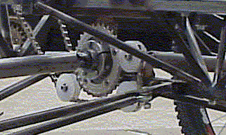
From the internal hub shifter the chain goes to the roller clutch based differential unit. The differential unit provides power to the slowest wheel so that the buggy remains powered even if one wheel loses traction. The torque from the roller clutches is transferred from the outer casing to the universal joints, which is connected to the half shafts.
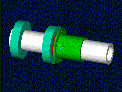
The half shafts connect the two universal joints that allow the axle to move with the wheel. Through the suspension travel the half shafts vary in angle and length. To allow the variation in length the outer universal joints are keyed along with the half shaft. At the wheel the universal joint is attached to the stub axle, which supports the wheel in the upright.
The stub axles are made of large hollow steel tube, and attach to the disk brake mounting holes. The disk brake holes make for convenient mounting points to the axle, as the hubs are readily available for purchase. The disk mounting holes are strong enough because the braking loads are the greatest torque loads, so they are plenty strong for the pedaling torque.
The 94mm/74mm cranks are known as microdrive or compact cranks. With recent attempts to race with two chainrings instead of three many different chainrings are available in numerous gearings. The 58mm pattern will fit 20 and 22 teeth rings, and the 94mm will fit 29 to 32, and 42 and 44 tooth chainrings. Although 32 tooth rings are the standard, 29 and 30 tooth gears can be ordered. QBP (Quality bicycle Products, a wholesale distributor) sells 30 tooth rings. 29 and even 28 (must have special bolts to use 28t) tooth gears are made by Ritchey and some other companies.
On of the biggest problem with the old buggy were chain derailments. These occurred for two reasons improper chain alignment or improper chain tension. To solve the tension and alignment problem in the crank to internal hub shifter chain line an eccentric bottom bracket was used.
Design Notes
The need for a reliable and easy way to tension and align the chain between the cranks and internal hub shifter was needed. This is very similar to the rear end and drive train of a bike, however we only have one gear so we do not need a derailleur shift and therefore do not have a chain tensioning device. If the gears are not properly aligned then when the buggy is pedaled the chain will derail. If the chain is tensioned too low then the buggy will work till a bump or turn causes the chain to swing out of alignment and result in a derailment. If the chain is tensioned too high then the chain, gears, and bearings will not function properly and will wear very quickly.
On last year’s buggy putting slots in the crank support members tensioned the crank to internal hub shifter chain line. This design did not perform well. The first issue was that the bolts on the internal hub shifter could not be tightened enough to keep the crank supports from sliding resulting in a non-fixed distance chain line. Another issue was that when the cranks were rotated for folding the chain line became shorter. In the end the slots were difficult to tension and would not remain tensioned.
This year we examined a couple of options. The same pulleys used to tension the internal hub shifter to drive axle could have been used. These however would have been hard to mount since the crank supports were small and at weird angles. In addition they could have interfered with other parts when the cranks were in the folded position.
The other option examined was the use of an eccentric bottom shell. This is a part commonly used on single speed bikes. It is composed of an enlarged bottom bracket shell that has been cut and bolts mounted to clamp down on a cylindrical aluminum insert. The insert has a hole that is tapped and accepts a normal bottom bracket placed off center in it. A bottom bracket is what holds the cranks to the bike and allows them to spin. By adding or removing links of chain and spinning the insert the chain can be tensioned to account for different chain length requirements such as is required for different gear combinations.
This design has been tested and is a tried and true method for tensioning chains in similar situations to the one we encountered. In addition to being able to rotate, the insert can slide laterally to help with chain alignment. Another benefit is the commercial availability of all involved components. The only down side is a moderately heavy design. Since the buggy would not be ridden much the bottom bracket used was the most inexpensive one we could find at a local bike shop.
Fabrication Notes
Since eccentric bottom brackets can be purchased at any bike store fabrication was minor. The shell should be purchased uncut. Then weld on the bolt clamps, tubes, and anything else that is going to be attached to it. Then cut the shell so it can clamp down on the insert. This will ensure that the shell does not warp during welding and that insert will fit properly.
In the purchasing of the bottom bracket make sure it is compatible with the cranks. Either splined or square taper joints do not make any difference for our purposes because the low usage. We recommend using the cheapest design that has different length bottom brackets, this year we used square taper. Also when placing the bottom bracket into the shell, make sure it goes in the correct direction, with the fixed cups on the drive side.
Performance
We experienced no chain derailments during testing or racing. This in itself is a testament of the perfect performance of a properly set up eccentric bottom bracket. The one problem we did experience was that the eccentric is not properly designed and does not complete adjust to any size chain. If the chain happens to result in the shell being at its limits there is a small window where proper tensioning cannot be achieved. This was frustrating and was fixed by changing to a slightly different size gear that was needed anyway.
Lessons Learned
The biggest thing we learned was to make sure that all members that were going to be welded to the shell were attached before it was cut. We did not do this and as a result the shell warped making it hard to adjust. In addition, really examining the specifications of the eccentric bottom bracket to make sure that it will be able to be fully adjustable.
Internal Hub Shifters
 With the complications of the buggy needing to fold, a robust shifting system
was desired. Derailleurs are vulnerable to damage, move the chain line,
and there is a high chance that the chain may come off during assembly. The
use of an internal hub shifter has many advantages over derailleurs. The
chain line is fixed, the chain length is fixed, and there are no derailleurs
that must move around during folding.
With the complications of the buggy needing to fold, a robust shifting system
was desired. Derailleurs are vulnerable to damage, move the chain line,
and there is a high chance that the chain may come off during assembly. The
use of an internal hub shifter has many advantages over derailleurs. The
chain line is fixed, the chain length is fixed, and there are no derailleurs
that must move around during folding.The gearing is idealized so that the middle gears would be used most frequently. Within the net gearing ratio, torques are minimized prior to the shifter hub to reduce loads on the shifter. The Shifter hub is only able to withstand a limited amount of torque. For this reason the smallest possible gear is placed on the body of the shifter hub to build as much torque after the hub.
Chain Guides / Tensioners
Introduction / Design Goals
 One of the primary problems with many buggies, including the 2001 buggy is
keeping the chain from derailing. A derailed chain means the buggy
has to stop until the chain is fixed, or in our case finish the course under
half power (unless the other chain derails as well). In some cases,
a derailed chain might require the rider to get off the buggy to fix it, and
incur a ground penalty. Keeping the chains properly tensioned and guided
is therefore of paramount importance to finishing the race cleanly and quickly.
One of the primary problems with many buggies, including the 2001 buggy is
keeping the chain from derailing. A derailed chain means the buggy
has to stop until the chain is fixed, or in our case finish the course under
half power (unless the other chain derails as well). In some cases,
a derailed chain might require the rider to get off the buggy to fix it, and
incur a ground penalty. Keeping the chains properly tensioned and guided
is therefore of paramount importance to finishing the race cleanly and quickly.
Design Notes
Last year, chain tension on the front (the model for both halves of this year’s buggy) left much to be desired. Between the cranks and the hub shifter, the adjustment was achieved by slotting the tabs attached to the crank support tubes. This worked horribly. Because the cranks have to rotate, they cannot be bolted securely down. In addition, There is sufficient force on the crank supports to move them even if they were bolted firmly. The result was that the cranks shifted back and forth, and the chain was still not properly tensioned.
The problem of tensioning the chain from the cranks to the hub-shifter was solved on this year’s buggy by the eccentric bottom bracket. We needed only to make sure we had proper gear alignment, and we would not have to worry about derailments.
The other chain, located between the hub shifter and the roller clutch assembly, also had tensioning problems last year. Tension was achieved by sliding the entire roller clutch support assembly forward and back. Aside from being very difficult to do, this also failed to keep the chain properly tensioned. The force on the chain was often enough to move the whole assembly, and if the chain did derail (which it often did), it was exceedingly difficult to get back on. Based on these failures, we identified several qualities that would be necessary for a proper chain tensioning system.
1. The tensioning should be achieved on the slack half of the chain line.
Thus it would only have to withstand forces due to the actual chain tension
and not due to the motive force.
2. Chain tension should ideally be an independent system. That is,
other important buggy systems, including the roller clutch assembly and the
hub shifter should be placed where they belong, and not moved for the purpose
of chain tensioning.
3. Tensioning the chain should be a quick, simple, one-tool job.
We also realized that chain guides placed before the chain meets gear would help reduce derailments (this function is performed by the derailleurs on a bicycle). It would be ideal if we could incorporate our chain tensioners with chain guides of this type
Based on all these considerations, we decided our chain guide/tensioners would be pulley-style spinners that would be mounted in a slot that allowed their position to be adjusted. On the front, there would be only one, placed just before the chain reaches the roller-clutch assembly chain ring. It would be mounted vertically off of the bottom frame rail, and would slide in a vertical slot. On the back, three guides would be necessary to guide the chain around the roller clutch assembly for the reversal mechanism. Two of these would be mounted below the bottom frame rail on either side of the gear, and the third vertically above the one closer to the center of the buggy. This last guide would slide in a vertical slot to adjust chain tension. All of these guides would be on the slack half of the chain line so as to encounter minimal loads. The guides would be mounted on bearings to minimize frictional losses (this was of arguable necessity, and could be skipped if finances were tight).
The final tensioning goal was single tool adjustment. This was achieved
by using a T-slot nut in the slot. These are normally used to bolt
things to machine tables. This setup allowed the loosened, slid along the slot
and tightened effectively with one tool. We decided to use allen-head
bolts so the tension could be adjusted with an allen-wrench.
machine tables. This setup allowed the loosened, slid along the slot
and tightened effectively with one tool. We decided to use allen-head
bolts so the tension could be adjusted with an allen-wrench.
Fabrication Notes
We decided to use ultra-high molecular-weight polyethylene to make our chain guides out of because of its resistance to wear. The bearings were the smallest, cheapest ones we could get that would fit a ¼-20 bolt. We got two bearings for each guide with OD’s of 0.625”. In order to be able to tighten down on the bearings, we had to make a spacer to go between them, and small OD washers between bearing and the slot. The slots were made about an inch and a half long in 0.040 chro-moly sheet. This much adjustability was only really necessary in the front where the tensioner simply deflected the chain line from the side. On the rear, where the chain wrapped 180 degrees around the tensioner, only ½” of adjustability is required to account for a 1” link. The slots were supported with more 0.040” sheet and welded to the lower frame bar. On the rear, the non-adjustable guides were bolted through holes in the 0.040” plate instead of through slots.
When the chain guide mounts were first constructed, they were equipped with clamping mechanisms that allowed them to be bolted to the frame, and adjusted as necessary. We found that they did not clamp well enough to resist being moved by the chain tension. Therefore, once we decided where they worked best we welded them onto the frame.
The guides themselves were turned on a lathe out of a piece of 2” diameter UHMW PE we purchased from McMaster. Putting the bearing-reliefs in was a little tricky because they had to be put on both sides. Therefore, one side had to be done after the guide was cot off the stock. It was pretty difficult to hold the guide properly in the lathe, therefore one of the bearing-reliefs was a little larger than 0.625”. This made some of the chain guides wobbly, and therefore less effective than they might have been. In the end, the bearings probably weren’t necessary, and we felt like the guides might have been better off if we had just drilled a bolthole in them and attached them with shoulder bolts.
Performance / Lessons Learned
The chain guides worked flawlessly. Since they were welded on we have not experienced a single chain derailment. Aside from the shoulder bolt idea mentioned above, we recommend using an identical technique on future buggies.
There was some argument about whether welding the chain guides onto the
frame was necessary or appropriate. The argument is that the more things
you weld to the frame, the less replaceable your frame is. There was
also the worry that many welds on the lower frame bar would weaken the already
highly loaded member. Though the clamps that were made for our chain
guides where ineffective, a better design could allow them to be clamped rather
than welded. In the end, none of our fears were justified, and the
trussing probably strengthened the frame beyond any chance of failure.
Still, a clamping mechanism could be considered for future buggies.
The next other two ideas considered were using conventional bike chain in a different way than usual. The simplest is to simply run the chain in a figure eight pattern around two gears. This design is used on many recumbent however they do not ride over rough terrain and tend to have longer chain lines so a slight misalignment in the chain is less noticeable. This design was rejected for two reasons. First the chain would have to be tensioned in some way. Second the chain would have a tendency to derail because a perfectly straight chain line would be impossible.
The final idea examined was the use of pulleys to wrap the chain in the reverse direction around one of the gears. This idea would be a little more complex than the figure eight design however the pulleys used to reverse the chain could also be used to tension and align the chain. For these reasons this design was chosen. A schematic of this type of design is below (file “reverse idea” on black CD in “all pictures” folder).
The pulley locations were placed on the non-drive side of the chain loop and what was required to get the chain too loop around the gear. The pulley arrangement could have been arranged in any configurations to allow clearance around other parts of the buggy. One of the pulleys was attached so that in addition to its role as a guide pulley it could be adjusted to allow for chain tension adjustment. Using a slotted bolthole allowed for this adjustment
Roller clutches were used for the effective differential because they offered many advantages over standard differential units in performance, cost, complexity, and weight. A roller clutch will always power the slowest wheel, where as a differential will power the wheel with least resistance. If a wheel powered by a standard differential were to lift off the ground, it would spin freely and the wheel in contact with the ground would recieve no driving force. This was not desirable in the event that a wheel lift off the ground in the race, as it would make a rider power less. A roller clutch based differential would prevent this effect.
A main tube was used to house the roller clutches. The main tube was bored precisely to the diameter required for the roller clutches. The roller clutches were press fit inside the tube. On the outside of the tube a shaft collar is used to clamp on the drive gear. The shaft collars also serve the purpose of constraining the roller clutch assmbly in it's frame mounts.
The inner shafts that spin inside the roller clutches are made of hardened steel shafts. The insides were bored out to allow the universal joint to fit inside the end of the shaft. The universal joint and the hardened steel shaft were then keywayed to transmit the torque.
The frame mounts for the roller clutches use two needle bearings and 2 thrust bearings. Sealed cartridge ball bearings were considered for use in this area, however their use was deemed unnecessary. The ball bearings would have been considerably larger, heavier, and had much more friction. The needle bearings were much lighter, and rolled very easily. The disadvantage of the needle bearings were that they didn't support axial loads, so thrust bearings were used, they weren't sealed, and they didn't come with an inner race. because the loads placed on the bearings were low compared to the bearings' rating, and the axial loads were almost neglegible, needle bearings could be justified. The 2001 buggy used needle bearings and it they worked very well, so there was little reason to use ball bearings in this location.
The bore of the main tube was machined to the tolerances specified by torrington. The tubes were cut to 5" long, slightly longer than the width of four roller clutches. The inner shafts were cut to 2.5" each, so they would be fully in contact with the roller clutches. The shafts were purchased as presicion hardened shafts, exactly to the specs and tolerances of the roller clutches.
It is very difficult to bore the main tube to the specs required by the roller clutches. it may take a few attempts, but it is possible. The surfaces were honed after machining to make them smooth and to bring them to the final tolerance.
On the 2001 buggy the half shafts were overbuilt in many areas, and as a result were much heavier than they could have been. A primary goal was to minimize the weight of the half shafts, while ensuring that they would be strong enough for the torques they would experience. The 2001 buggy also had the half shafts welded to different components, preventing them from the potential to be rebuilt or easily replaced. Ease of manufacture and replacability was another goal.
The halfshaft experiences greater sress at the ends where the key or pinned joint creates a stress concentration on the half shaft. To minimize the weight while maintaining sufficient strength throughout the half shaft, the ends of the half shafts are made much thicker than the middle section.
The universals were chosen based on their torque rating, resulting in universals with 1" outer diameters. They are manufactured by Curtis, and purchased through Kaman. The outer front universals were custom ordered with 45 degree misalignment clearance, increased from the standard 35 degrees. The extra clearance would allow for sharper turning and large suspension induced misaligment.
The stresses were approximated in the shaft by assuming that the maximum torque that could be transfered to the the shafts would be limited by the roller clutches. This effectively limits the torque to around 1500 in-lbs. The stress in torsional shear is given by T*r/J, where T is the torque, r is the outer radius, and J is the polar moment of inertia. The maximum predicted shear stress is then calculated to be around 29ksi, providing a reasonable factor of saftey for surface scratches and a reasonable fatigue life.
The half shaft keys were constructed by first cutting a slot through the full wall thickness of the shafts using the horizontal mill. The key-piece, made from 1/8" steel sheet, was then fit into this slot with a portion of it sticking out past the inner diameter acting as the "key". The "key" was aligned and held in place by an aluminum cylinder with a keyway cut 1/8" deep. The key was then welded to the shaft, and then the surface was ground to the contour of the half shaft. This permitted the key to be structurally attached to the half shaft, and it permitted the key to be placed only partially down the length of the half shaft. A typical keyway could not have been broached the full length of the half shaft, they are too long.
The key-way of the U-Joints was also fabricated using the horizontal mill. The cut was made 1/8" deep, with enough clearance as to not catch on the key in the half shaft.
The torque is transferred from the inboard U-Joints to the half shafts with a simple pin. The hole for this pin was drilled though the shaft and the U-Joint at the same time to make sure the proper alignment was achieved. This was done on a mill with the U-Joint clamped to the shaft with a vise grip.
It is difficult to bore the entire length of the half shafts, as they are very long. It is important to use a sharp cutting tool mounted in a very stiff boring bar. At the length the boring bar must be extended it is important to try to minimize vibration to ensure a good surface finish inside the halfshaft.
 Once of the continuing issues with the ’01 buggy was the stub axles. They
were made too small in diameter for the loading conditions and subsequently
bent or sheared off under heavy loading. This year we set out to make purposely
overbuilt stub axles. If something were to fail in the drivetrain we did
not want it to be the stub axle. With that in mind we built large outside
diameter axles with hollow insides to create the largest moment of inertia
while minimizing weight.
Once of the continuing issues with the ’01 buggy was the stub axles. They
were made too small in diameter for the loading conditions and subsequently
bent or sheared off under heavy loading. This year we set out to make purposely
overbuilt stub axles. If something were to fail in the drivetrain we did
not want it to be the stub axle. With that in mind we built large outside
diameter axles with hollow insides to create the largest moment of inertia
while minimizing weight.A problem with last year’s design was that the stub axle had a pin that transferred torque to a disk right at the highest bending stress point.
This year we wanted to eliminate that problem. To do this we welded a flange to the disk and put a keyway along the inside length. This way we could transfer the torque inside the hub and away from the high bending stress area.
To keep the flange from moving laterally it was welded to the stub axle. With the flange disk bolted into the disk brake holes on the hub this constrained everything outbound of the upright.
To keep the stub axle positioned laterally inside the upright, we made a round spacer for bolt clearance and then held the whole apparatus in place with an external grooved snap ring. The flange and spacer was pulled up flush against the bearing race and a snap ring was snapped on the far side to prevent lateral movement.
To cut the snap ring groove we first assembled all of the pieces into place and then carefully scribed a line at the edge of the bearing race on the axle where we wanted the groove to sit. It was essential that we placed this groove correctly to eliminate slop. The actual cutting of the groove was done on a lathe and eyeballed to the correct position. To cut the groove we narrowed a cutoff tool to the specified width and cut the specified depth (given by McMaster).
As for the overall design, it was not very user friendly. Perhaps some thought could be put into ways to make it easier to take apart and replace wheels etc.
Most of these decisions stem from last year's experience. Because last year's stub axles were prone to bending a hub that could accept a 20 mm bolt through axle was required. This would allow for a larger (and stronger) stub axle to be used. We decided to use a similar disc brake setup as last year's buggy (see brakes section) so we required disc brake hubs. 26-inch wheels were used because they were the current standard for mountain bike wheels providing the widest range of available parts.
The first thing chosen on the wheel was the hub. The hub would serve as the connection between the buggy and the rest of the wheel. Front hubs were used because we did not have any use for the cassette body that comes on a rear wheel. In order to help counter the lateral loads on a wheel in a turning situation the angle between the left and right spokes should be increased and the length of spoke should be shortened. To accomplish this the hubs chosen had the widest spoke flange (increasing spoke angle) width with the largest diameter spoke flange (reduce spoke length). In addition the hub had 36 spoke holes, the largest number available for a standard mountain bike wheel. The hub chosen was the Dimension front disc hub.
The rim was the same used as last year, Sun Mammoth. In addition to having a large box cross-section for rigidity, they are very heavy, meaning they consist of a lot of metal, making them stiff. A lighter stronger rim could have been chosen however the cost would have been much greater. The Sun Mammoth is a very inexpensive and strong rim. The rim was laced to the hub using large 14- straight gauge spokes.
Tires were chosen based on availability and cost. Since our buggy wheels do not need to lean into corners like a bike tire, our only goal was to get a fast rolling tire. An ideal tire for this is a semi-slick mountain tire. The center section is solid so the tire will roll without the usual small bumps because of text that mountain bike tires have. These were out of stock at time of our order so we chose to use the Ritchey Z-Max 2.35 tires. These have a relatively solid center tread and were low in cost.
We chose to use Avid mechanical disc brakes again this year. Disc brakes were chosen because our design does not have any structural members that could support a rim mounted braking system and the use of disc brake hubs allowed direct attachment of the disc to wheel. Mechanical discs were chosen over the more powerful hydraulic brakes because mechanical disc brakes are lighter, less expensive, easier to fit, and easier to adjust than hydraulic disc brakes.
Because the buggy folded at the center, as opposed to completely separating, the brake cables could be run to allow the front driver to control the rear brake. Tandem bike cables were used to get the extra length we needed.
To eliminate some of the problem with the cables getting in the way they were run internal on the handlebars. This created a cleaner look and kept the cables from getting caught on everything. Where the cables exit the handlebars a gusset was used to reinforce the bar and a slot was drilled and ground to allow the cable to pass through the bar. The cable was then zip tied to the frame down the length of the buggy and out the A-arms to the brakes. It is important to note that the brake cables should be routed and cut only when the buggy is completely done. Try not to create sharp bends in the cable as this causes more friction and less control of the brake.
The 94mm bolt pattern chainrings have been found to be the smallest that will fit over the body of the shifter hubs. The smallest gear is placed on the shifter hub to reduce the gearing to the optimal range. The cog on the shifter hub is limited to what is available by the manufacturer. At the cranks the largest feasible gear is used, to minimize the torque at the internal hub shifter. The gear on the drive axle is then made reasonably large to make the gearing low as desired.
Spiders were designed to mount the gear to the internal hub shifters. The spider has a 94mm diameter bolt pattern with five 10mm holes. The spider mounts to the holes for the spokes on the hub. The hubs were 36 spoke, with 18 holes per flange. The spider was designed with holes to line up with the holes on the hub flange. The spider on the drive axle was similarly made with a 94mm bolt pattern.
The Final gearing for the front:
The spiders were made on the rotary table on the mill. The bolt pattern
and cuts were specified by radial and angular dimensions. Extra narrow track
chainring bolts were used to hold the chainrings to the spider. The bolts
must be narrow since they are only holding one chainring, instead of two,
to a thin sheet of steel.